@barry
Forum Replies Created
-
AuthorPosts
-
 BarryKeymaster
Yah, I obviously had a brain cramp while trying to answer too quickly. 😳
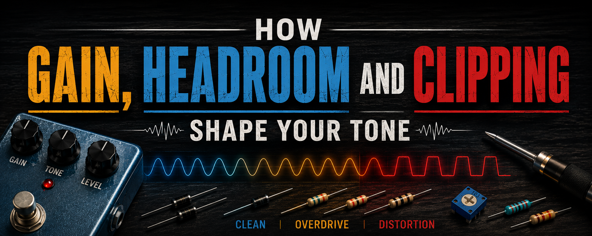
D7 and D8 are the hard clipping diodes in this circuit. Also much easier to mod.Thanks brd
BarryKeymasterVery Nice and thanks for sharing.
BarryKeymasterD3 through D6.
I really have no specific suggestions other than perhaps trying LEDs, but clipping is very subjective. Experiment and have fun.
BarryKeymasterNew GuitarPCB Guide:
click the image above to download the guide.
Electrosmash.com Articles
Unfortunately there is no expected return of their site.
It is NOT a complete backup of the site. If you want a more comprehensive archive visit archive.org.
The ElectroSmash archives have been an invaluable learning resource for me over the years and have helped shape the engineering behind the entire NostalgiTone line. Whether you’re building your first pedal or designing your own circuits, they’re well worth the read.
Pedals
- Back Talk Analysis
- Big Muff Pi Analysis
- Boss CE-2 Analysis
- Boss DS1 Distortion Analysis
- Dallas Rangemaster Treble Booster Circuit Analysis
- Dunlop Crybaby GCB-95 Circuit Analysis
- EMG81 Pickup Analysis
- Fuzz Face Analysis
- Klon Centaur Analysis
- Marshall The Guvnor Analysis
- MXR Distortion + Circuit Analysis
- MXR Dyna Comp Analysis
- MXR MicroAmp Analysis
- MXR Phase 90 Analysis
- ProCo Rat Analysis
- Sitar Swami Analysis
- Tube Screamer Circuit Analysis
- Vox V847 Analysis
- You can Build the Perfect Germanium Fuzz Face
Chips
Amps
BarryKeymasterThanks Jay. I agree 100%. That is definitely in the works.
BarryKeymasterThose look fantastic and thanks for sharing.
The trim pot is a necessity for the Fuzz. You could even mount it as a pot for a quick change. I also like how the Bass pot can be used to adjust your tone between say a Strat and Les Paul. I roll off Bass for the Les Paul and add some for the Strat.
BarryKeymasterHere is a Marsha Tone as part of a dual combo of high gain builds which may be helpful for comparison.
BarryKeymasterThe 4V readings throughout parts of the audio path are normal for this type of op amp circuit and do not indicate a short between power and audio. It is also normal to have no direct continuity between the power jack and those points since the VB reference voltage is established through the resistor network rather than through a direct connection.
It may be worth experimenting adding a capacitor in parallel with R14 since this is a fairly high gain circuit and since it is a very easy modification.
Squealing can also be commonly related to wiring layout, grounding, lead dress, shielded wire routing, or even the op amp being used.
One thing to keep in mind is that taking a verified circuit to random forums or FB groups can sometimes generate a lot of conflicting theories from people unfamiliar with the actual design.
If that doesn’t work out I would do all of the common troubleshooting steps.
- Verify the issue only with two known good cables and a proper isolated power supply, and with no other pedals connected in the chain.
- Since this is a fairly high gain circuit, avoid turning every control fully up. Start with the Tone control near center since it is also part of the Active gain structure, then see if there is a range of settings where the squeal disappears or improves. Try gently moving the wiring around with a pencil to avoid power and audio wires running parallel or too close together.
- power it using the battery test
- Also, do not underestimate the possibility of a cold or questionable solder joint. High gain circuits can amplify even very small connection issues into squealing or unstable behavior. I would strongly suggest reflowing all solder joints on the PCB, pots, jacks, and off-board wiring even if they visually appear OK.
If after testing everything as suggested above and reflowing the entire board and you still have squealing you will need to post some clear, well lit photos showing both sides of the PCB and the off-board wiring so we can try to see what is going on..
BarryKeymasterRe-flow solder joints.
BarryKeymasterI left you this message when you wrote that your Angry Llama was working.
BarryKeymasterI am glad you got it sorted out. Thanks for reporting back.
A quick tip when building pedals is to remember that the pedal itself is only one part of the overall signal chain. Things like pickup output, guitar type, amp settings, power supply, and even playing style can all have a significant effect on how a pedal circuit responds.
With regard to the SWAH, this is one of those circuits that really needs to be dialed in to your particular guitar and setup. In short, it is not going to “quack” on every setting combination. You will need to spend a little time finding the settings that work best with your rig.
Oh, and always bend the leads on glass diodes with pliers and not your fingers. The glass can crack and ruin your project.
BarryKeymasterAlso, just flip the switch and tell me if it goes away.
If none of that helps try something for me and just lift one leg of R9 (whichever leg is more convenient) out of the circuit and then try it.
BarryKeymasterThe value filters noise. Does not affect tone. Do not use tantalum.
When I said not my circuit I meant original design.
BarryKeymasterMake sure the Boost in the middle is not cranked. Not my circuit but it is called Angry for a reason.
If that doesn’t help and you have spare components you could try changing C4 from 100p up to 330p or 470p
BarryKeymasterCongrats on getting it up and running! That is definitely a more ambitious choice of circuits for an early build. The standing resistors look great too.
Most important thing is that it works and now you have a solid foundation moving forward from here.
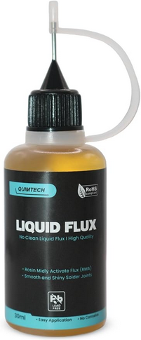
Here’s a helpful tip for soldering jacks: apply a small amount of liquid flux to the jack lugs before soldering. It helps the solder flow evenly and makes the job much easier. This works for input/output jacks, power jacks, or really anywhere you want cleaner, easier solder joints.
Great Job! What’s next?
BarryKeymasterThanks guys!
In some ways, 17 years seems like a very long time. In others, it really doesn’t. I guess it depends on the day.
We’ve lost a few shining stars along the way, and I still think about them all the time.
The business was originally started so I could work from home and raise my kids. That mission was accomplished, and now the next goal is making it to retirement.
I truly appreciate each and every one of you who has been part of the journey along the way.
BarryKeymasterNever happened to me, or saw anything similar here.
The only thing I can think of is a short, or perhaps the Green blew out leaving the Red only.
Verify the value of your CLR. Then I would check for a solder bridge, and also probably just replace the LED with a pre-tested one using a 3v coin battery. Must be common anode.
-
AuthorPosts