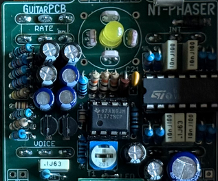
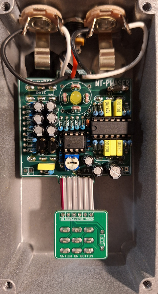
@barry
Forum Replies Created
-
AuthorPosts
-
 BarryKeymaster
Depending on the value of the CLR that was used you may have instantly blown the previous LEDs.
I would try another new LED. You can pre-test with a 3v coin battery.
If that doesn’t help I would test all of the connections between the 3PDT and main board with regard to the LED using your DMM in continuity mode. If you verify by pre-test the LED is working and you solder it back in and it still doesn’t work then i would look at these three things in order. Soldering an LED with minimal contact can also introduce a cold joint.
- Blown LED
- LED lead not actually connected
- Cold joints on 3PDT daughterboard
- Broken connection between main board and switch board (ribbon connections)
One additional test would be to temporarily connect the LED cathode directly to any ground via jumper (leave the Anode connected). If the LED lights, then the issue is definitely somewhere in the switching path between the 3PDT and the main board.
BarryKeymasterWhat value of current limiting resistor are you using on the 3PDT?
It’s too hard to see but looks different.
BarryKeymasterThe LDR itself is very simple and has no polarity, so orientation doesn’t matter. If it did, it would be clearly noted in the build document, the schematic, and indicated on the PCB silkscreen.
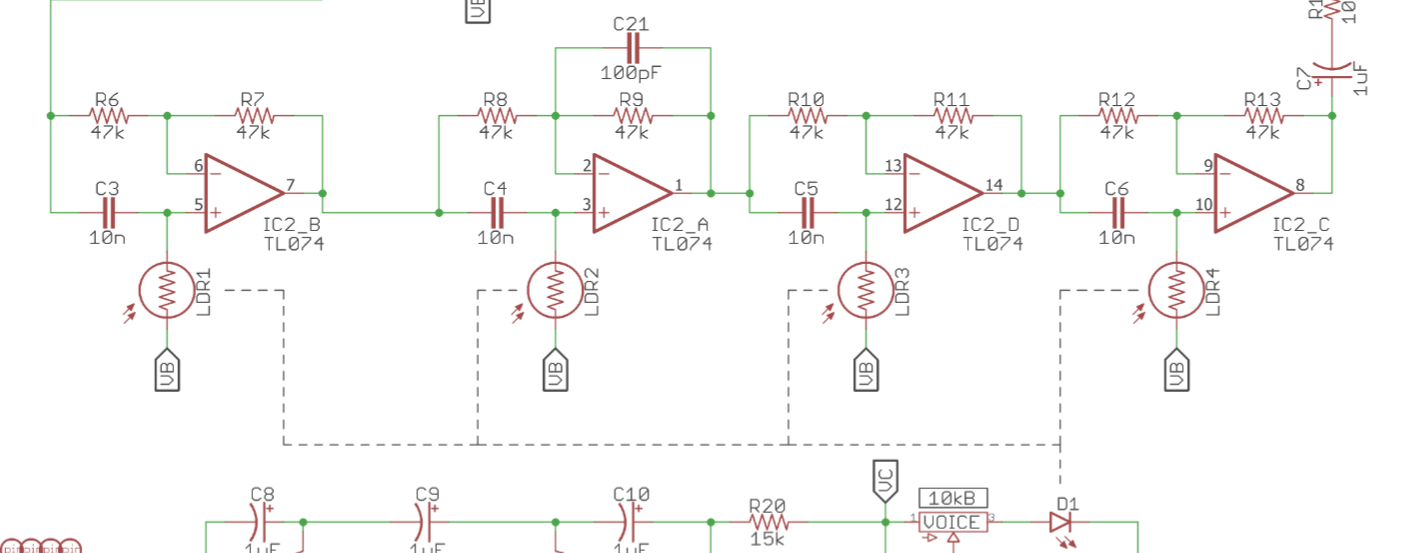
If you check the schematic in the build document, you’ll see how that each LDR ties into a phase-shifting stage, which is the core of the circuit. Each stage shifts the phase of the original signal by up to 90°.
If you want to learn more about what a Phase Shifting Stage does you can read about it here:
https://www.electrosmash.com/mxr-phase90
I would not be over-critical about the LDRs and install them as seen in the photo in the build document.
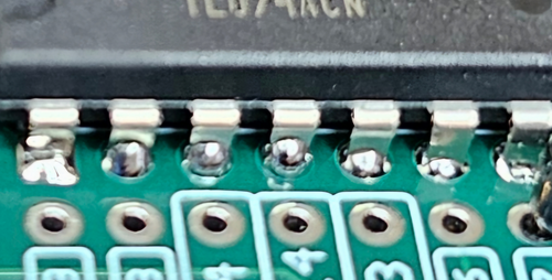
Looking at this photo, it seems like there are balls of solder on the component side of the PCB. That’s a concern, as it can lead to cold solder joints. It only takes one of those to cause the build not to work.
It should just be enough to flow into the joint and not push through to the component side.
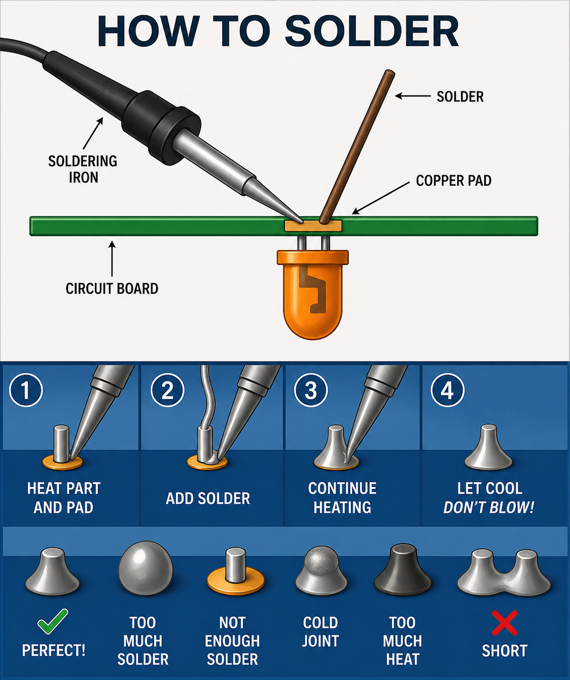
It is OK for some to come though to the component side but I felt this is worth pointing out. I would leave it alone for now but make sure the solder side of the PCB looks like the reference solder joint above.
April 28, 2026 at 9:28 pm in reply to: Band of Gypsys finished with GPCB aluminum face plate! #38979BarryKeymasterYes, that’s what I mean and thanks for posting.
A picture is sometimes worth a thousand words.
April 28, 2026 at 8:43 pm in reply to: Band of Gypsys finished with GPCB aluminum face plate! #38977BarryKeymasterGreat build—looks awesome, and thanks for posting it.
I don’t think people always realize how small these are compared to a 1590DD. That’s a ton of pedal crammed into a really tight space.
BarryKeymasterIt is perfectly fine to solder IC Chips to the PCB if you are good at doing it without over heating them. I do it all the time. I did say above in my post that the first things to solder are the Diode and Sockets.
Previous post:
Another good reason for socketing is in case you solder the chip in the wrong orientation or want to switch out a bad chip.
Anyway I would just go ahead and build it up but take your time and carefully plot your course.
BarryKeymasterThe Phaser is one of the few PCBs that requires standing resistors unless you’re using 1/8″ resistors (which most people don’t have on hand). It’s simply the only way everything will fit on the board. So if you’re using standard 1/4″ resistors, you’ll need to install them vertically.
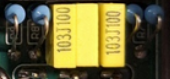
As mentioned earlier, it’s best to start with the lowest-profile components first. Just keep in mind that once installed, standing resistors will sit about as tall as the film capacitors.
For this build, a good order of assembly would be to start with D2 (diode), then move on to the IC and transistor sockets. After that, install the small ceramic capacitors (pF values), followed by the standing resistors and film capacitors. Finish up with the electrolytic capacitors and the LDR section.
Here are a few additional reference photos:
Resistor orientation doesn’t matter, so no need to worry about which way they face (see above).
It’s also a good idea to use the BOM as a checklist while you go—it helps catch anything you might otherwise miss.
Even experienced builders make mistakes now and then, so take your time and don’t rush it. And be sure to read through the guides—they’ll save you a lot of trouble.
These ones most of all!
BarryKeymasterHi and welcome.
There are several beginner guides on the Guides Page.
You can access through the Main Menu Bar up top or:
Scroll down and find the tings you need and take your time.
BarryKeymasterAhh, very nice indeed.
BarryKeymasterThe results are in for the NostalgiTone Panel Contest — thanks to everyone who took the time to enter.
I ended up combining five sets of rankings from different individuals to arrive at the final placements, based on the criteria outlined (overall presentation, build execution, and panel integration).
Final Results
🥇 1st Place — Zoso (jmgrabowski)
This one stood out for its overall balance and execution. Clean layout, strong visual cohesion. This took priority over the “2112” build since only one of them could be awarded a prize but was also a fine submission.🥈 2nd Place — Phaser (jasonwickersham)
A very strong showing here that clearly resonated across multiple voters.🥉 3rd Place — 70’s Triple (Matt)
Probably the most creative entry of the group. The theme was nailed and it definitely had the most visual personality.Honorable Mentions
- DSOTM (Max)
- BRIT-800 (Tiger1050)
Both of these had solid ideas and execution.
Prizes will be issued as one-time use discount codes as outlined in the original post. CONTACT ME for your PRIZE CODE.
Thanks again to everyone who participated — really appreciate the effort that went into these builds.
BarryKeymasterThese all look fantastic — thank you to everyone who submitted an entry.
I’m going to take a few days to review everything and gather a few additional opinions so I can put together a fair overall ranking.
I’ll post the results shortly after that.
BarryKeymasterVery nice Harbinger!
BarryKeymasterBarryKeymasterCongrats!
The trimmer is for setting the bias of the chorus. There will be a fine spot where you will hear the best chorus. Sounds like you found it. The build document has been updated.
Is this going to be a contest entry?
BarryKeymasterLooks great and thanks for sharing.
Be sure to post the other ones when you get them done.
BarryKeymasterBarryKeymasterI’m extending the NostalgiTone Panel Contest for one more week to give everyone a bit more time to finish up builds and get entries in.
Deadline is now April 17th.
-
AuthorPosts