@barry
Forum Replies Created
-
AuthorPosts
-
July 18, 2026 at 1:07 pm #39465
 BarryKeymaster
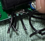
In the meantime I would take some time and carefully clean up the bottom 6-pin connector pads on the reverb side of the board.
I’d use a good Soldapullt-style solder sucker first, then follow up with some copper desoldering braid to remove as much solder from the holes as possible. Just be careful not to apply too much heat or linger too long, as you don’t want to lift or damage the pads.
Once the holes are cleaned out, I’d use individual wires instead of another ribbon cable. Insert each wire from the component side until the PVC insulation is flush against the board, then solder it from the opposite side and trim the excess just like you would a component lead. This helps prevent stray wire strands that could cause a short. Even if the holes aren’t completely cleared, individual wires are much easier to install one at a time than trying to force a new ribbon cable through.
Also if you bend Reverb brick leads to gain easier access be sure to reflow them all after bending it back.
It will not work with it like that above.
July 16, 2026 at 8:57 pm #39456BarryKeymasterAlso I was going to say that you need to make sure you have a power supply providing at least 100mA of current or it won’t work.
July 16, 2026 at 2:08 pm #39452BarryKeymasterAt a glance I cannot make out IC6 well enough to confirm the correct orientation.
The other thing I would check is that all voltage regulators are firmly seated since sockets can create intermittent contact. You can make a few minor back and forth bends in the leads to assure they are secure in the sockets. Also tell us what brand of L78L05 that you used for all three.
I would also set all three volume trimmers to their center positions.
Hopefully Billy can spot something.
July 16, 2026 at 12:12 pm #39450BarryKeymasterYes, I understand what you are referring to. My point was only that the scratch is very unlikely to be the source of the problem. As Billy pointed out, the power trace runs underneath that area, so it is not affected by the scratch.
July 15, 2026 at 11:43 pm #39447BarryKeymasterThe white line at the top is just a decorative silkscreen border. I cannot say if you may have created a ground island though just below that (honestly I doubt it since the center pad has connections on either side of the scratch). I can’t tell how bad it is from your photo but you will be able to see that much better in person.
I would do a full re-flow as a cold solder joint is the number one offender in most forum posts.
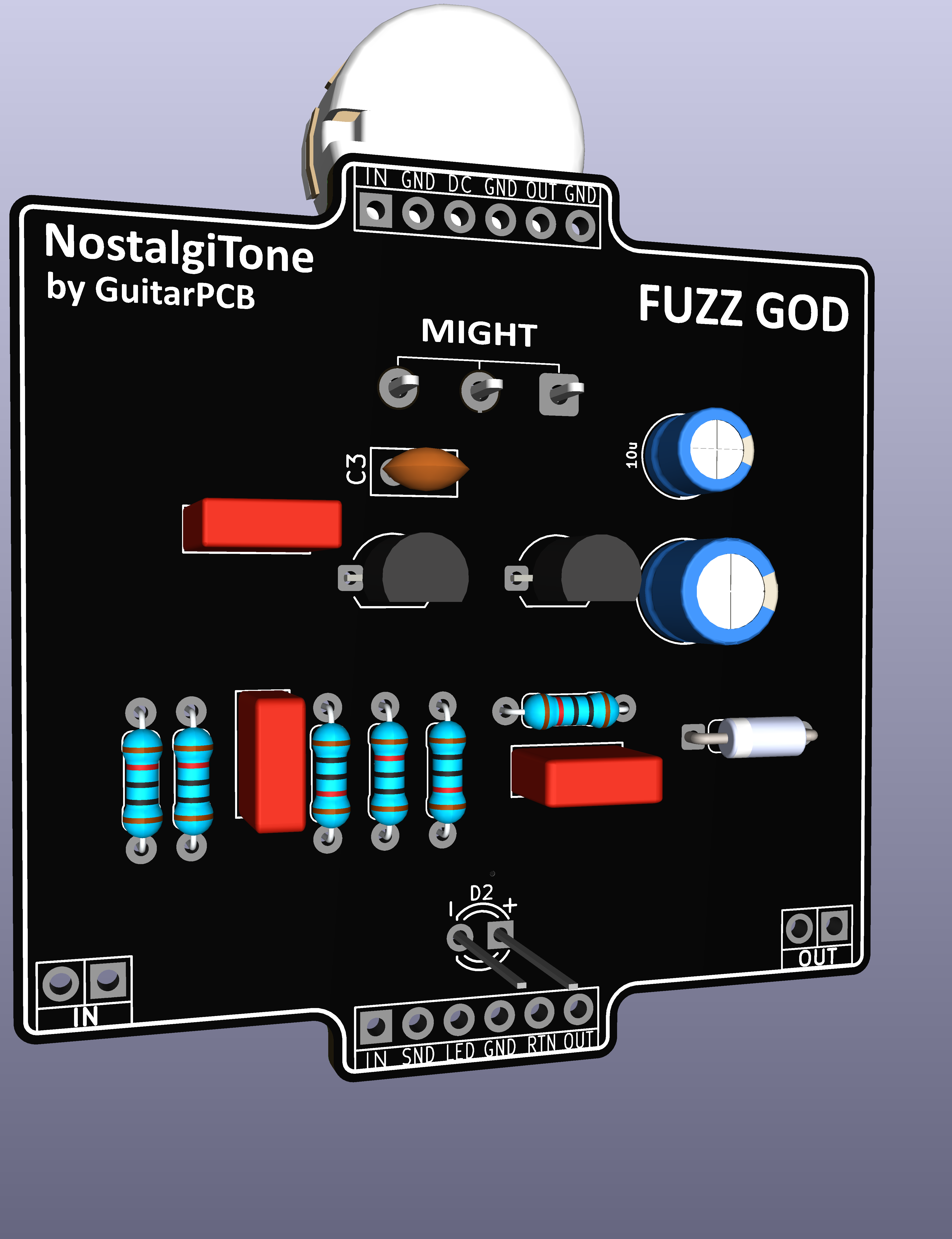
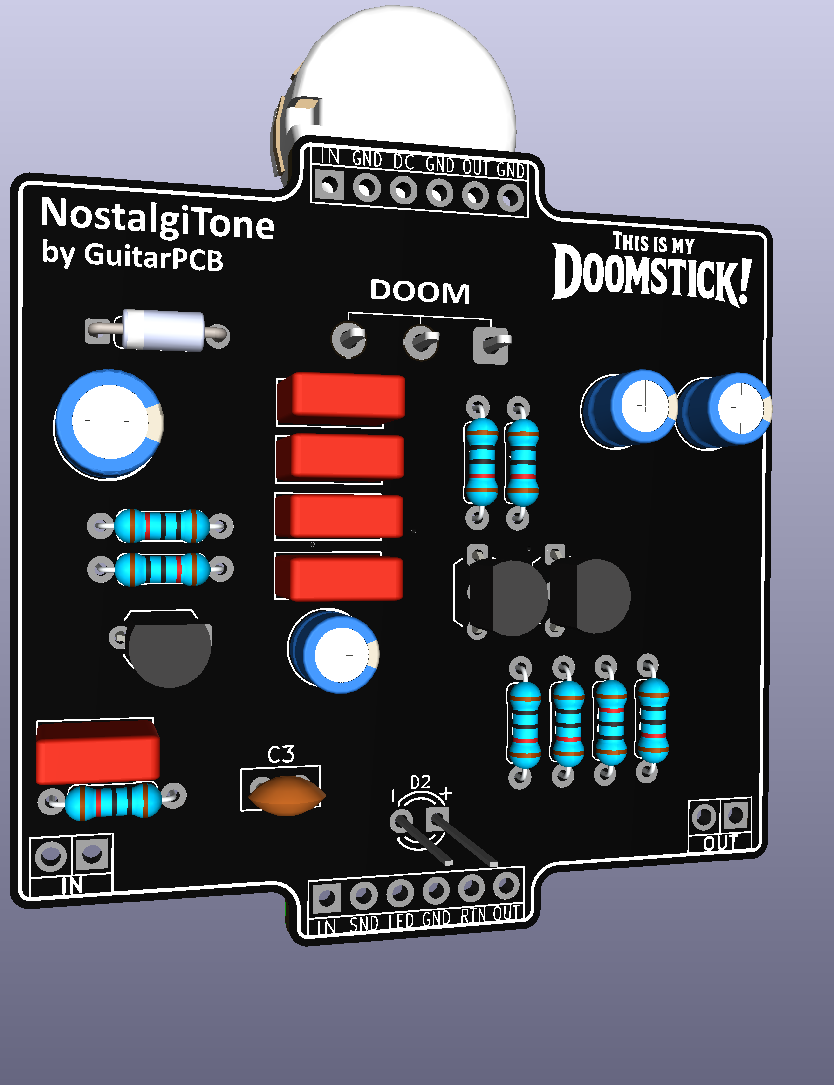
Here is a complete build with gut shot to check against yours which can sometimes be helpful.
July 12, 2026 at 5:34 pm #39441BarryKeymasterVery nice! Thanks for sharing.
July 10, 2026 at 12:50 pm #39428BarryKeymasterI have not personally tested any clear coats on the panels, so I can’t recommend one over the other.
I would suggest testing on a small area first, as acetone can potentially affect the printed silkscreen ink or finish.
I would like to hear your results though.
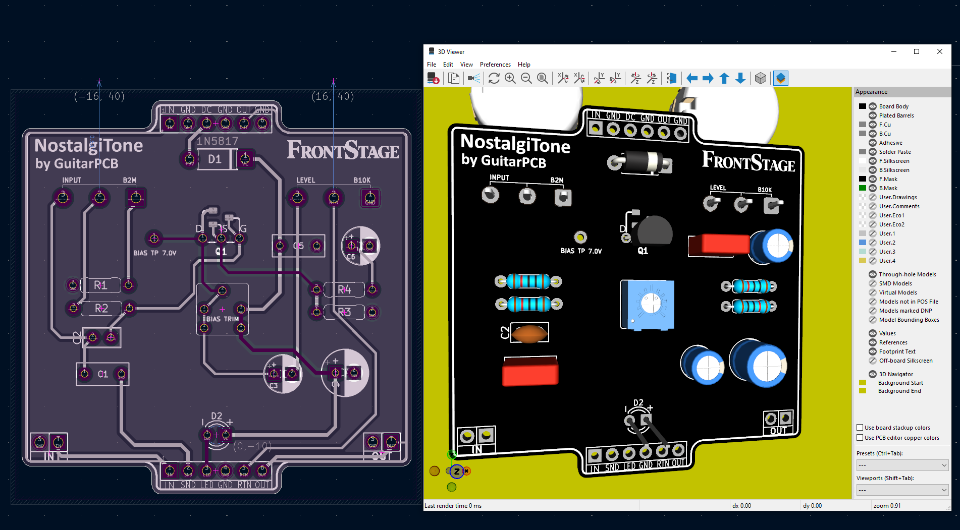
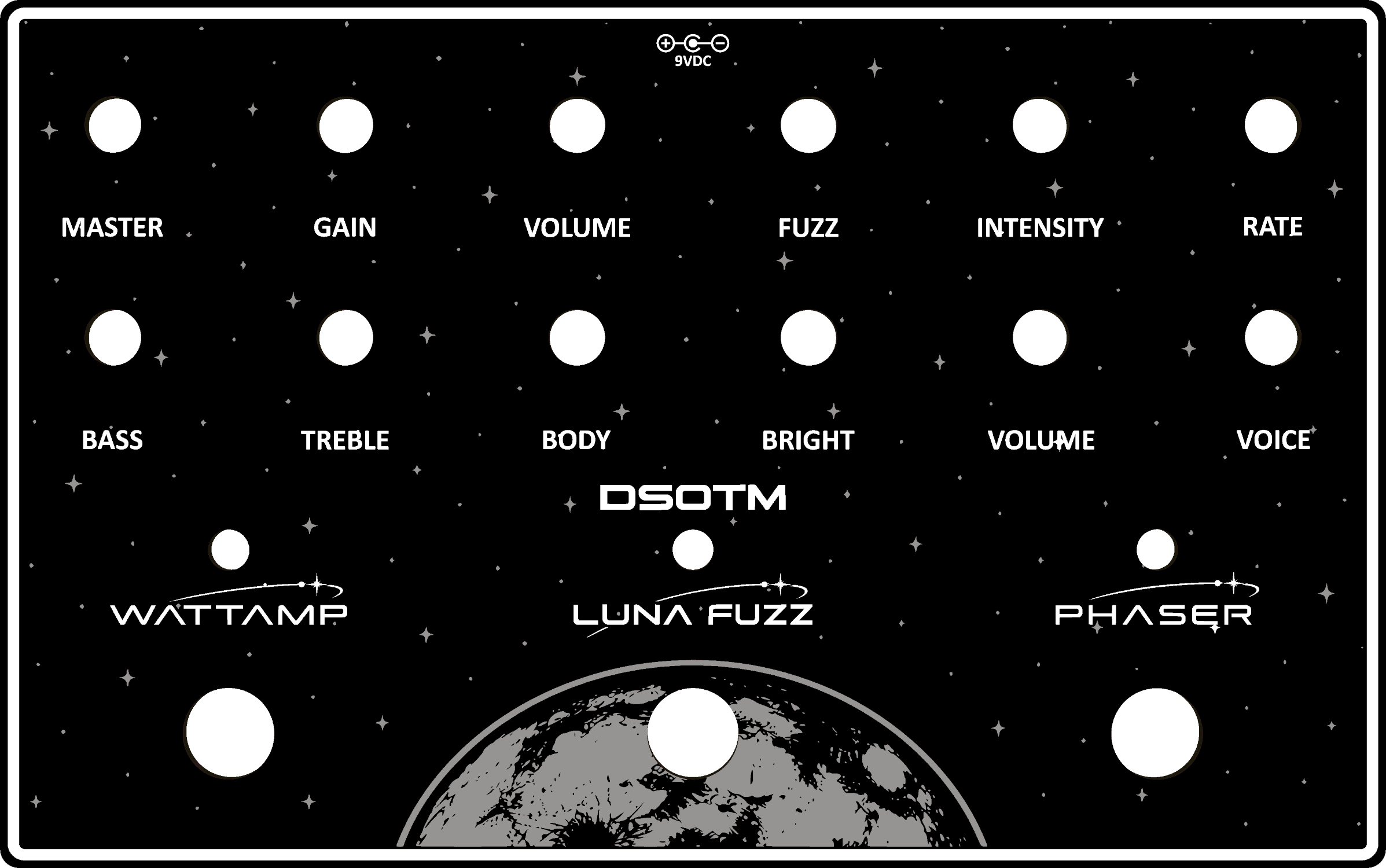
July 7, 2026 at 7:26 pm #39413BarryKeymasterI wanted to give you a behind-the-scenes look at something I’m especially excited about. This is FrontStage, a new NostalgiTone project currently taking shape. While it’s designed to stand on its own, the real magic happens when it’s paired with DumbleTone in a future Dual Combo. With onboard order switching, you’ll be able to place either stage first and discover ways to use this previously unavailable.
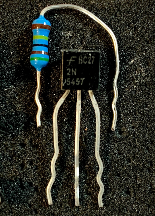
One design feature I’m incorporating is SMD pads for the JFET, making it easier to support both through-hole parts and modern SMD replacements as component availability changes over time.
I hope you enjoy these occasional behind-the-scenes previews as much as I enjoy creating them. There are many others waiting.
As always, thank you for supporting GuitarPCB. Every order helps fund the development of new projects like this one, and I truly appreciate it.
July 4, 2026 at 4:00 pm #39408BarryKeymasterVery Nice Indeed! This is a fantastic sounding Distortion.
Thanks for sharing.
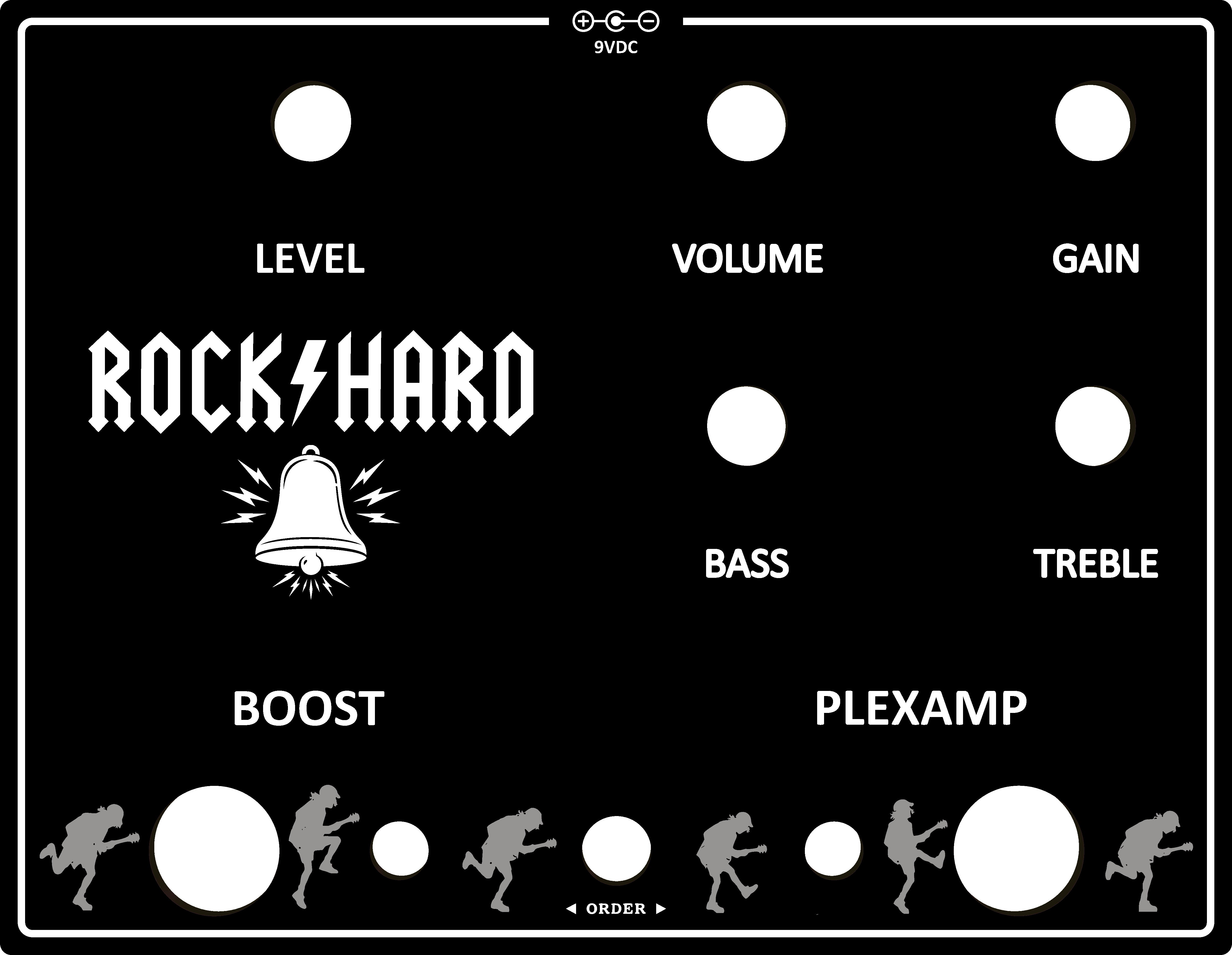
July 3, 2026 at 3:27 pm #39403BarryKeymasterThat turned out fantastic! Thanks for sharing the build and the great feedback.
I’m really glad to hear everything went together so smoothly. Enjoy the ROCK⚡HARD!
June 26, 2026 at 7:28 pm #39382BarryKeymasterThanks Steve.
And another I just finished today.
I hope that helps with the request of “keep em coming” from OP jmgrabowski
June 26, 2026 at 1:22 pm #39380BarryKeymasterLooks great and thanks for posting!
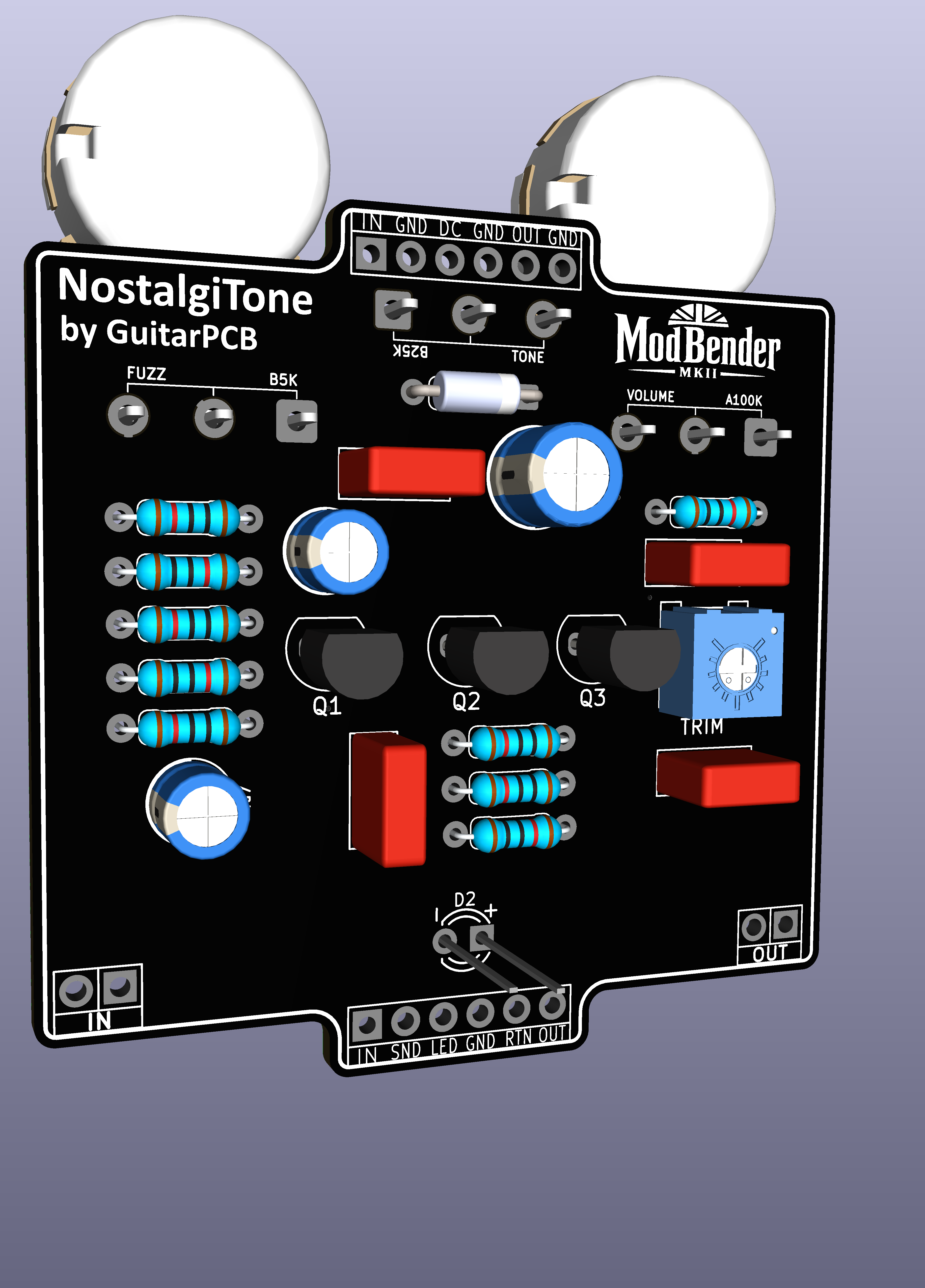
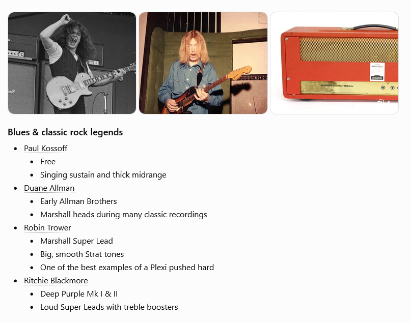
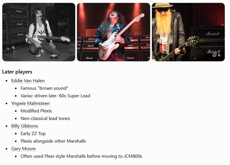
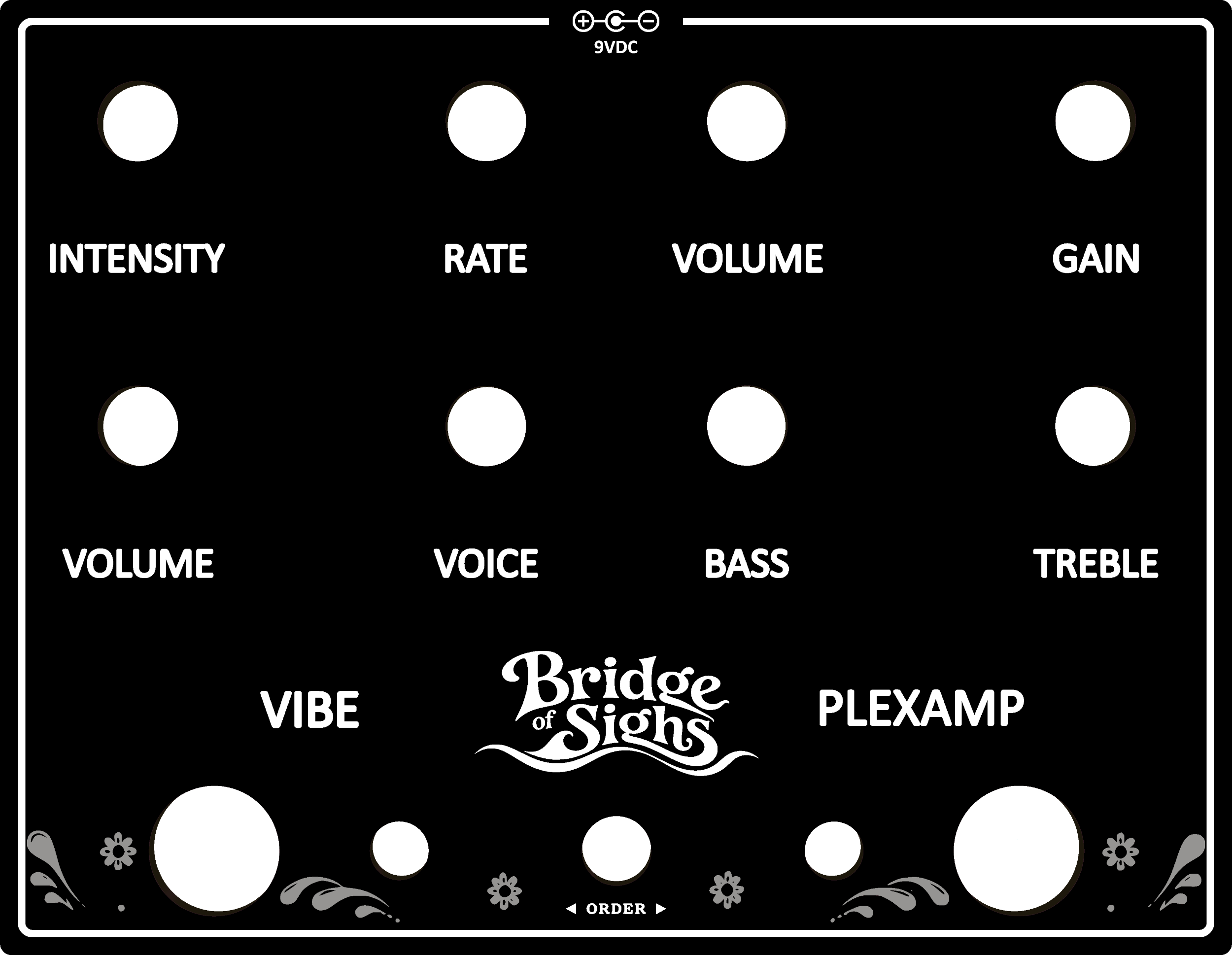
The PlexAmp is such a great piece in the NostalgiTone line that fills the need for any situation requiring a Marshall Plexi tone.
Here are just a few notable examples over the decades.
A true workhorse for the NostalgiTone line.
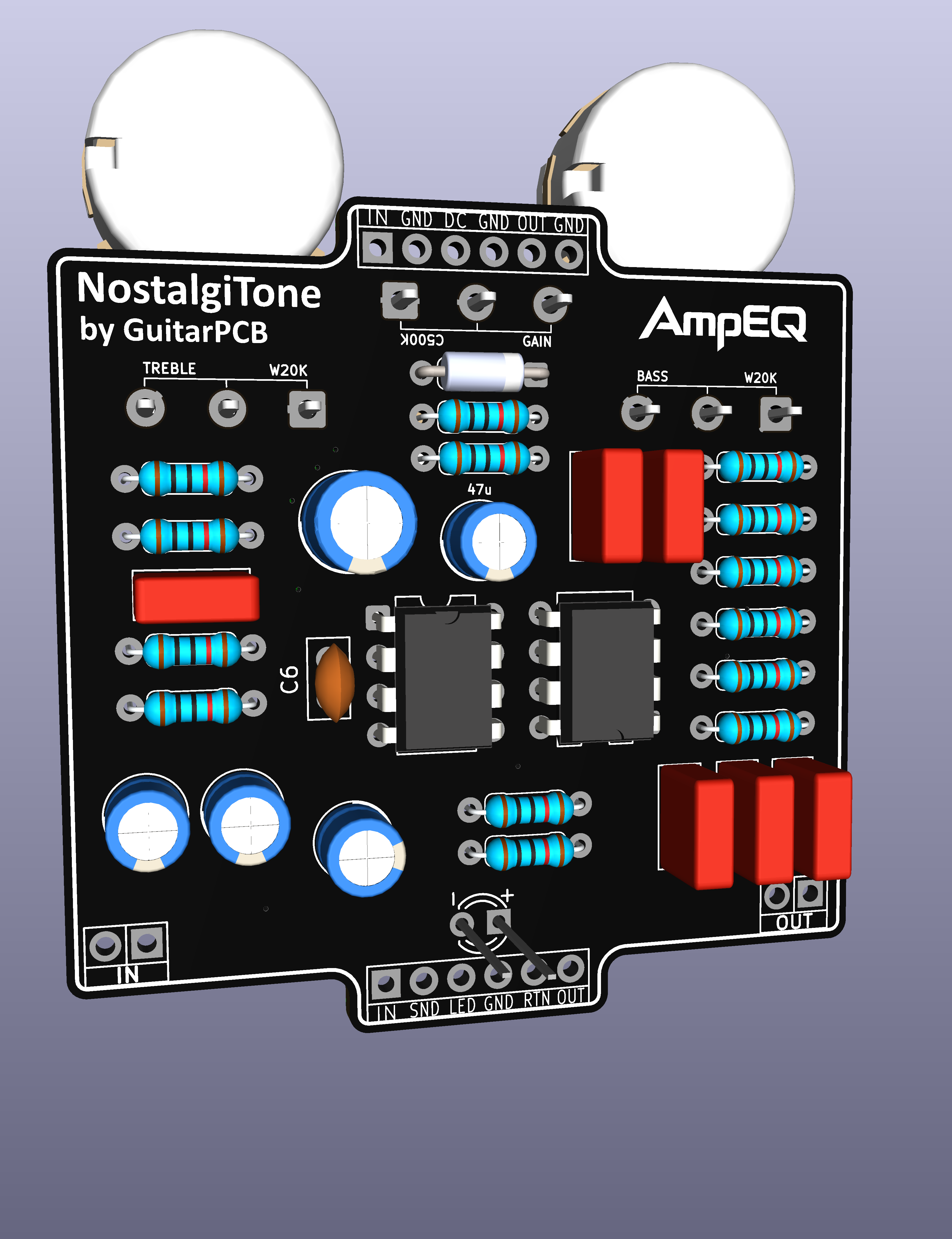
As for “keep them coming” here are just a few of the many I am working on.
June 17, 2026 at 7:59 pm #39292BarryKeymasterThese new Plates will be available soon.
(see video demo at the bottom)
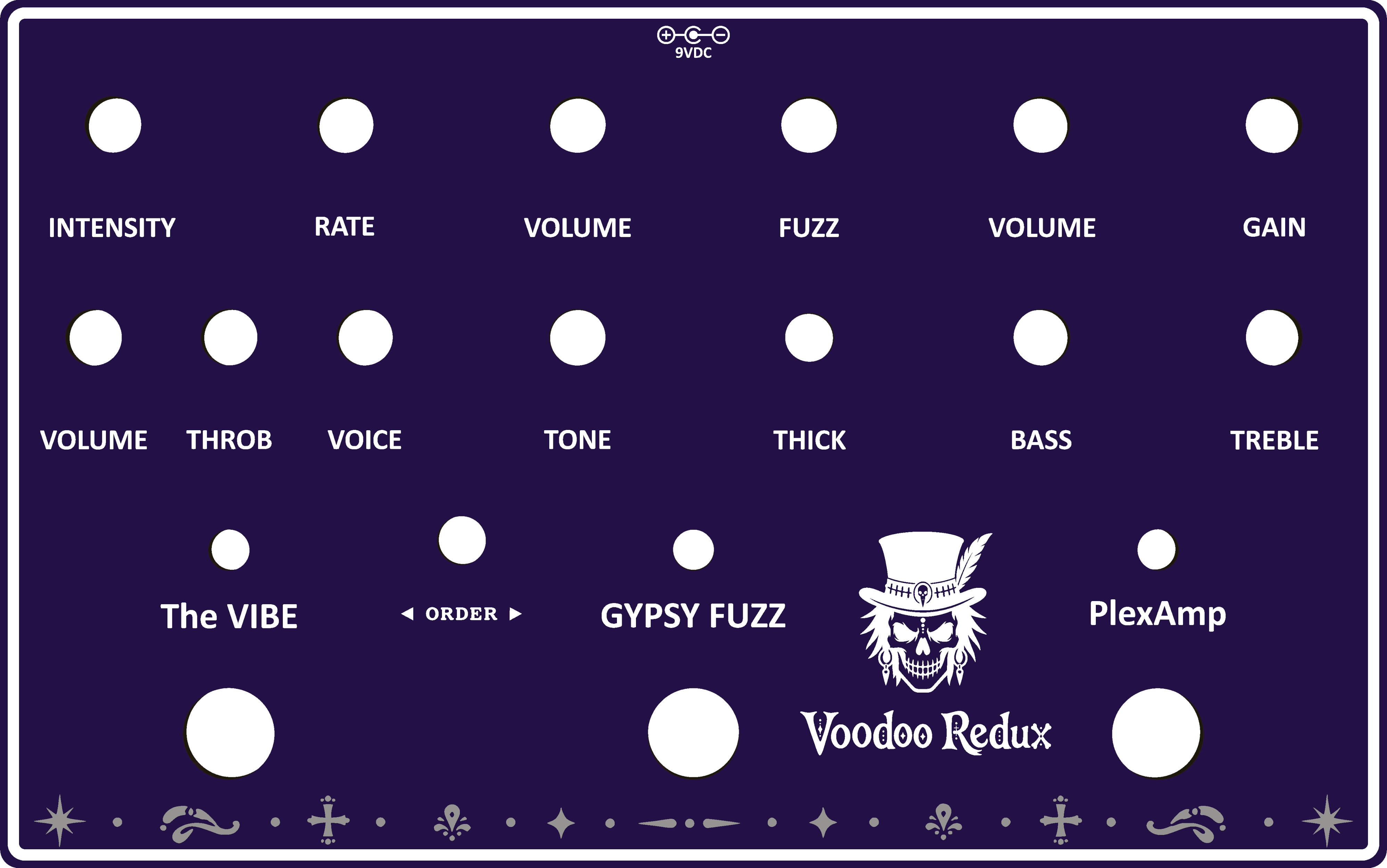
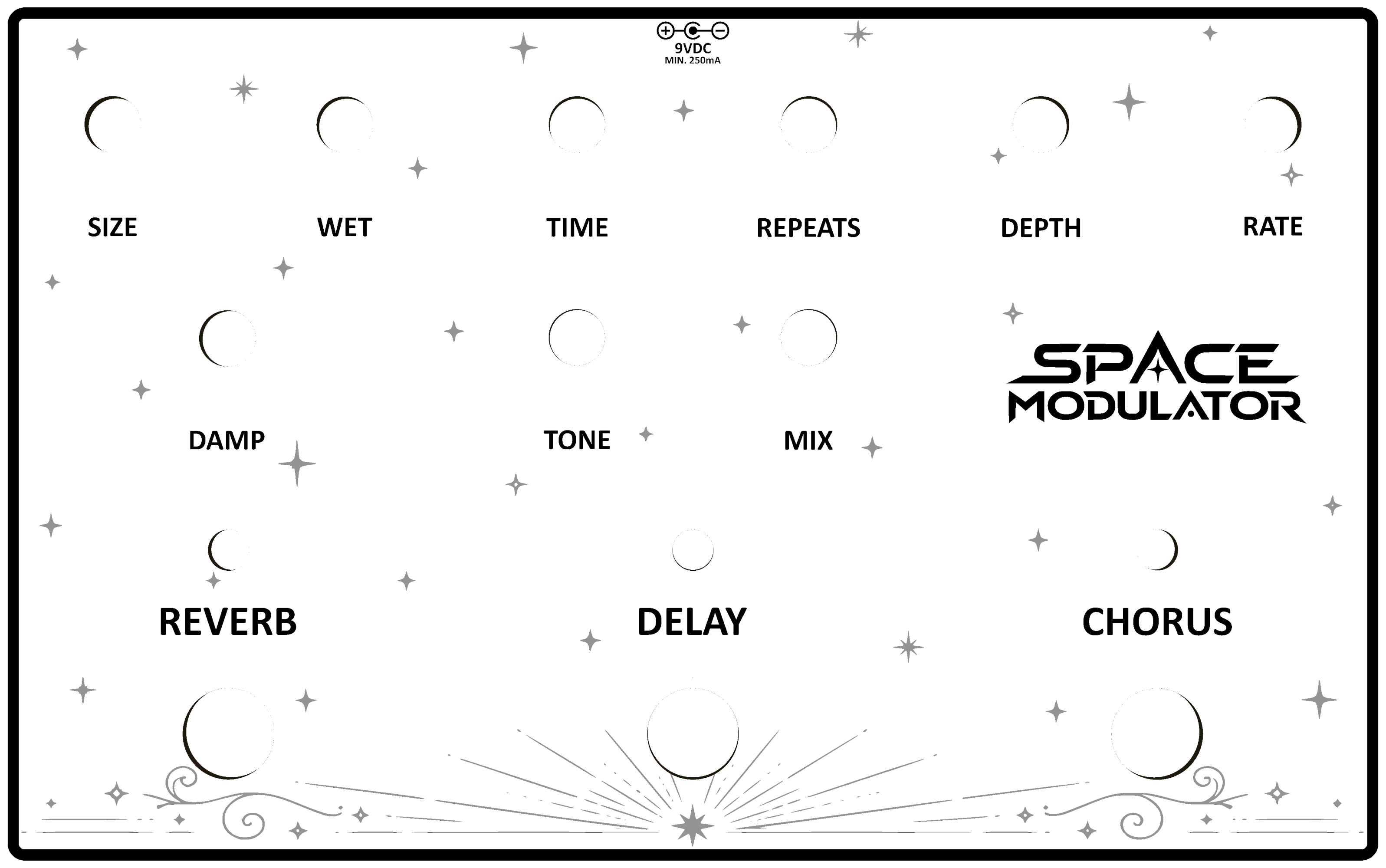
Here’s a quick look at the new NostalgiTone silver tinned-pour artwork.
The metallic silver portions aren’t printed ink—they’re actually part of the PCB itself. As the viewing angle and lighting change, the artwork takes on different appearances while the labels and controls remain clear and easy to read.
Any gray artwork shown in the catalog or shop images represents this metallic silver finish. The effect is difficult to capture in photos and video, but looks fantastic in person.
June 10, 2026 at 10:54 pm #39251BarryKeymasterVery nice, and thanks for sharing!
I’d be interested to hear more about some of the tones available, particularly when the combo builds are used in tandem with the order switching. It would be great to hear which combinations have become your favorites.
June 10, 2026 at 8:37 pm #39249BarryKeymasterI agree! That said, D7 and D8 are easy to switch.
June 10, 2026 at 8:02 pm #39247BarryKeymasterYah, I obviously had a brain cramp while trying to answer too quickly. 😳
D7 and D8 are the hard clipping diodes in this circuit. Also much easier to mod.Thanks brd
June 9, 2026 at 4:34 pm #39238BarryKeymasterVery Nice and thanks for sharing.
-
AuthorPosts