@barry
Forum Replies Created
-
AuthorPosts
-
 BarryKeymaster
Hey Mathew,
Since you provided some art (thank you) I think it may be helpful for people to get through the check out process to understand a few things with this particular image. Please correct me if I am wrong on any account. I will try to make some kind of guide to follow since there are a lot of steps.
I am not sure about your gloss layer but I can edit this or anything else once I know the details.
see section in large red font below.
————————————————
You need to create an account with Tayda to be able to upload ART files or Drill Template links and save them to your account.
For purchases through Tayda using this particular artwork you need to:
Go to this link: https://www.taydaelectronics.com/hardware/enclosures.html
Add a Black 1590DD enclosure to the cart.
You will also need to add a 1590DD drill service as well if you want drilled.
Go to this link:https://www.taydaelectronics.com/1590dd-custom-drill-enclosure-service.html
That is where you will add the drilling service to your cart.
Go to this link: https://www.taydaelectronics.com/hardware/enclosures/enclosure-uv-printing-service.html
Then you will need to purchase a 1590DD UV Printing service, and Gloss layer service:
- Enclosure UV Printing Service (choose enclosure size you wish to order) – In this case a 1590DD.
- Additional Service for Gloss Layer Enclosure Custom Printing Service – This puts a protective coat over artwork.
Checkout and pay.
After waiting at least 15 minutes, visit this link:
https://drill.taydakits.com/dashboardThis is where you can assign your uploaded UV template as well as your Drill template link.
Mathew this is where you can provide any details about your artwork to me and I can edit or update as needed.
Name your Design, select the enclosure size, and answer ‘Yes’ to all the questions (the files have data in the color, white, and gloss layers). Choose a Varnish or Matte topcoat finish, accept all terms and save your design.
In the Orders section, click ‘Create Job’ (see Figure B in picture below).
Select the enclosure you ordered and attach the UV Printing, Design and Gloss services you purchased to the Enclosure Job, as shown below. Click ‘Submit Box Job’ when finished.
The print job is now pending. Be sure to check back in a day or two to make sure there are no issues from the graphics department, as they will leave a message here if there are any problems. Your order is now in production!
Obviously you will have to adjust what is written in the images above to be pertinent to your own enclosure since the images are only examples and contain enclosure names like 1590B etc. which is not correct for this job.
BarryKeymasterImpressive looking build with beautiful artwork. Could you share your thoughts on the diverse sounds you can achieve with this combo? I’m sure you’ve found it offers much more than just Pink Floyd tone.
BarryKeymasterWell done and thanks for sharing!
That is a very nice looking enclosure.
BarryKeymasterThey are designed to add gain to suit different rigs, pickup types, and outputs. If you use single-coil, low-output pickups, you can increase the gain. The “stock setting” is minimal for both, but you can adjust each one slowly and incrementally with small turns as needed. Experiment to find your preferred level, or stick with the minimal stock setting.
I have updated the build document to be more specific.
BarryKeymasterThe first thing I did is start scanning your build when you mentioned the transistors.
I am not saying you are incorrect but when I saw the f and v reversed on the labeling it did occur to me.
BarryKeymasterI suggest using a standing trimmer especially since it doesn’t take up any additional space.
You could likely change your mind many times for many reasons.
BarryKeymasterGreat job and thank you for posting Chuck!
The only thing I feel I need to mention is that the press-on letters for the Fuzz and Volume are reversed.
The f should be top right and the v top left. (easy fix)
BarryKeymasterThe only thing I would point out is the connection to the Tone TwEQ, and Emexar needs to be at the (T) pads and not ground at the IN and OUT sections. Make the necessary common ground connections between all circuits including +9v and audio jacks. There are plenty of extra pads on all PCBs to choose from to make that happen. Also the two main boards need to have a +9v connection as well as the 3PDT wiring board assuming that will be your Status LED location.
As Playsforfun points out, particularly when the Active EQ is first in order I would try to keep the overall volume level of the TwEQ at a minimal setting so as you are not creating undesirable clipping. Then TwEQ it from there. Much in the same manner as you would do with any EQ.
BarryKeymasterCheck your email for my response.
BarryKeymasterI meant you would need a new switch and wiring board. If you want it like it was designed to be.
You could also wire to a bare new 3PDT switch and include the CLR using one of the standard DIY guitar pedal wiring methods.
A cap is simply any cover you choose to use for the LDRs. You can attach four leads to a cap (either by gluing or soldering) and then solder it to the board to keep it in place. However, this is completely unnecessary. They were added because they take up “zero space” for those who insist on using a cap for unknown reasons, even though the back lid of the enclosure will do the same job. The pads are not connected to anything in the circuit.
BarryKeymasterThe 3PDT wiring board is backwards.
Wiring Diagram
You will need a new wiring board. I suggest carefully heating and removing the wires from the 3PDT board only, to avoid damaging the pads on the main board. Then, insert the wires into a new 3PDT board. Alternatively, you could use a new ribbon cable or wire, but ensure the pads are thoroughly cleaned out first. Be cautious when cleaning out the pads to avoid ruining them.
The four holes are for soldering a cap in place for those that feel they must have a cap.
BarryKeymasterAt a glance, R2 needs to be 820R (820 Ohms). It currently appears to be 820K Ohms (820,000 Ohms), which would definitely cause your issue.
Additionally, for the Status LED, use the non-white outer pad for the Cathode. The white pad is only for bi-color LEDs to indicate Off status. The center pad is your Anode. This is what is making you think the pedal is On when it is actually Off.
Also looking at C1 you are using a 10n instead of a 100n which will cut a lot of your Bass content.
BarryKeymasterTo be able to help we need photos.
Please provide clear images showing the top side, back side of the main board, the 3PDT switch, and the wiring connections to the jacks.
With these visuals, we can better understand the situation and likely resolve all your issues.
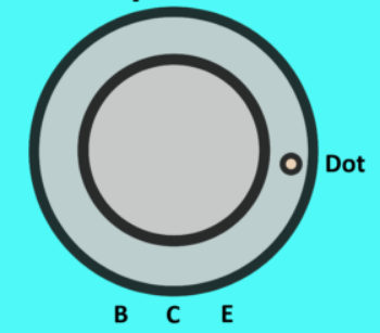
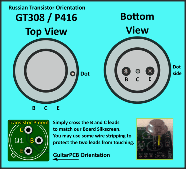
BarryKeymasterIf they are Russian the dot indicates the Emitter and the lead for the Base on the opposite side.
Otherwise the Tab indicates the emitter and they follow the silkscreen on the PCB.
BarryKeymasterMost Russian Germanium have a dot to indicate the emitter side. Then typically they reverse the Base and Collector from what we would expect like in the image below. Try looking up datasheets for confirmation. Remember Russian alphabet is different.
If they are not Russian look up datasheet.
BarryKeymasterIt is always good to ask first.
If you’re asking about the reason for grounding both jacks. It’s mainly for redundancy; if one jack fails or comes loose, the other will still be grounded.
The audio path goes from the main board (In and Out – T pads) to the 3PDT switch (Lugs 1 and 7), then to each Jack Tip from (Lugs 2 and 8) respectively. Make sure the T pads on the main board (for both In and Out) are used, since they are the audio path and the pad next to either T pad is for grounding each jack.
If this doesn’t address your question, there are also Beginner Guides below the build documents on the Guides Page that will help.
Also, post that NostalgiTone build in the “Show Off” section.
BarryKeymasterHow about Nostalgitone British and Blues Breaker combo, Barry?=)
You can contact me for a request and I can Invoice you.
Contact info is in the main menu bar. Hover over LINKS to see it.
-
AuthorPosts