@barry
Forum Replies Created
-
AuthorPosts
-
 BarryKeymaster
Love it!
Thanks for posting. Another great circuit that has slipped through the cracks of “TIME”. Just ticking away at the circuits that make up an old day.
November 10, 2025 at 3:19 pm in reply to: 🎁 Bonus PCB Program – Exclusive, Limited, and Free with Your Order! #37854BarryKeymaster🎸 Support GuitarPCB & Get a Free Bonus! 🎁
The Bonus PCB Program is my way of giving something extra back to builders who support GuitarPCB.
Every qualifying order of $15 or more gets one — no codes, no forms, just added to your order automatically.
💡 Why it matters: Every order, big or small, helps keep GuitarPCB relevant during these times. Your support truly makes a difference, and it’s greatly appreciated!
BarryKeymasterI have a real love/hate relationship with this one.
I absolutely love the circuit — it does exactly what it was designed to do — but I hate that it does not sell. It’s wild to me that it’s now obsolete.
I think the main issue is perception. Even though my demo clearly shows what it’s capable of, many people assume it’s not working properly because, at its core, it’s a noise-maker. With quick and careful adjustments, that I show right up front in the video by turning the Stab down, it can easily produce some truly great fuzz tones.
Thanks for sharing.
BarryKeymasterAwesome! Glad you like it.
Thanks for posting.
BarryKeymasterWhat is an “NT Paramix” ?
NT typically stands for NostalgiTone which is the latest and greatest GuitarPCB has been offering for the last 3 years however there are no immediate plans for a NostalgiTone version of the Paramix.
BarryKeymasterOne of my absolute favorites that has been on my pedal board since day 1, 15 years later.
Thanks for posting.
BarryKeymasterI would like someone to test out that Mod and report back their findings so I can add it.
BarryKeymasterLove this — and the whole Glowy Bit!
Sometimes a simple build is exactly what is needed. They have stood the test of time.
BarryKeymasterSince these type of transistors have a wide tolerance you can Adjust TR1 trimmer till you hear the best phasing typically around 12:00 – 1:00
BarryKeymasterBarry:
On the Ascension Boost, can I use a Mod board and switch between “Tight” and “All Frequencies” by jumpering C3, like on the Stage 3 Booster? So 10n and 220n?
Absolutely, and I would encourage it.
BarryKeymasterOne of my favorite “always on” Tone Boosters.
The NostalgiTone Ascension Boost is the current iteration of the Stage 3 Booster for anyone interested.
Thanks for sharing.
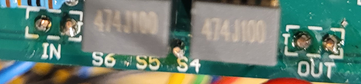
BarryKeymasterOn the IN and OUT pads be sure to verify that the Pad with the T in each group is your audio path and the Pad beside it is the ground. For the IN grouping the T pad is on the right and the OUT the T pad is on the left.
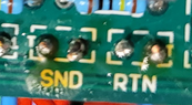
The same then applies to the Send and Return groupings.
Be sure that the Pad with the T is your audio path as the other is ground.
Beyond that I would be verifying all connections with a DMM for continuity including common ground and finally an Audio Probe.
BarryKeymasterThat is definitely a typo.
Also since it works with a TL071 that is also a good sign 😉
Thanks very much for letting me know. Build Document corrected.
BarryKeymasterVery Nice!
Thanks for sharing.
BarryKeymasterThe Mastodon Fuzz is just an extraordinarily good pairing with the Buff N Blend particularly if you want to use it on Bass. The short answer is that I didn’t create individual Buff N Blend wiring diagrams for every circuit I offer, as that wouldn’t be efficient since the Buff N Blend build document already covers the necessary wiring details. So, you can choose to use it with whatever circuit you wish.
BarryKeymasterThere’s already a 1M resistor on the main board for that. You can remove the extra 1M pulldown resistor from the footswitch.
For a pop, here are the first things to check:
- Ground continuity: Make sure all ground points are properly connected and everything shares common ground.
- Footswitch wiring: Double-check lugs for continuity to the correct place
- Solder joints: Reflow any that look cold or dull—especially around the jacks and footswitch.
- Electrolytic capacitors: Verify the polarity is correct on all electrolytics.
- Possible bad foot switch? Also note the Green Wire in the image below connecting lugs 1 and 6.
This is from the Guides Page. While the layout is not identical as there are many ways to accomplish the same thing it can help you check continuity using your DMM.
Since I can’t see the build myself, my strong instinct is that it’s a ground-related issue — possibly from incorrect wiring, a missing connection, or a cold solder joint. In that case, I’d start by carefully verifying all wiring and then reflowing every connection.
BarryKeymasterThe wiring diagram in the build document shows the preferred method.
-
AuthorPosts