Your Source for DIY Pedal PCBs and NostalgiTone! › GuitarPCB Forum › GuitarPCB Build Support › Paramix: zero sound
- This topic has 27 replies, 7 voices, and was last updated 8 months, 2 weeks ago by
 Barry.
-
AuthorPosts
-
October 29, 2025 at 6:48 pm #37736JohnnysmokeParticipant
I have finally built my Paramix V4 – I’ve had it lying around for several years. After the off-board wiring nightmare (LOL) was finally over, I powered it up and…
ZERO SOUND OUTPUT. Not even a hiss. Nada.
Question 1: Shouldn’t there at least be sound coming out of the “Dry” send or the “Wet” send? – because in my case, there isn’t. Nothing out of the output jack, either. Does not matter if the foot switch is engaged, or isn’t. And I mean ZERO sound. NO hiss, not anything. BTW, I even used patch cables on both send/returns, even both loops at the same time to make sure the send/return loops were closed. ZERO SOUND from the output.
I have spent 7 hours troubleshooting: I’m not an electronics expert by any means so checking resistances and/or pinouts on the opamp are a bit out of my league, but this is a low-count PCB and checking to make sure resistor/capacitor values is not much of an issue. I’ve completely taken everything out of the enclosure, and gone over the PCB with a fine-tool comb looking for soldering bridges, wires in the wrong places, etc.
I did check on the backside of the PCB with my voltmeter to make sure the resistors are the right values, and they are.
I have checked, checked, and checked again that all the wiring is correct. I even re-flowed a few solders here and there. Nada. I removed the T-Diddy Boost Mod (OH NO!!) and wired it ‘normally’ – still not a sound, no change at all.
The LEDs for the foot switch and kill switch work and light up correctly.
I was wondering if the TL074 might be suspect: I only have two, so I replaced it with the other one I have. Still no sound (I think I got them both from Tayda long, long ago)
If someone says “Oh, yeah, definitely the TL074” then I’ll order more. Otherwise, I’m building a sound probe tomorrow (I should have done so a long time ago, but this is my very first build that hasn’t worked. This is pedal build #13. I’ve also wired up 6 guitars and 3 basses without any issues. I’m not saying I’m an electronics expert by any means…but I’m decent with my Hakko) and I guess I’ll spend another hour or two on it.
Thanks for any help/ideas.
October 29, 2025 at 9:01 pm #37738AnonymousInactiveBummer … Posting pictures might be helpful.
October 29, 2025 at 11:18 pm #37748JohnnysmokeParticipantI thought of that, believe me. The off board wiring though…its like looking at an exploded bowl of spaghetti. Not a lot to see through the many, many wires on this puppy.
October 30, 2025 at 1:00 am #37749SteveModeratorJohnysomke, you might be surprised at how good some of the Admins/Members of this forum are with seeing a couple of pictures. Sure as heck can’t hurt. Just sayin’. 😉
October 30, 2025 at 5:52 am #37750brdModeratorJohnnysmoke,
My first check whenever a pedal doesn’t make any noise, is the input and output cables, go direct guitar to amp through both cables. That verifies the guitar and cables and amp.
Try plugging the guitar into the returns then, If you get sound, then your problem is in the front half of the circuit.
Then check voltage (DC) on the board, at the 9v+ pad and a ground. if that is good then verify the bias voltage (VB) that would be at pins 3, 5, and 10 on the IC, that should usually be around half the supply voltage, 4.5 volts. while your there write down the voltage readings for the other pins. pin 4 should be 9v. pin 11 should be 0v. NOTE: the pin to the left of the dot on the IC is 1 and you count down and over then back up..
If nothing obvious is wrong ,at this pint I would break out the audio probe. I’m not one of the guru’s here.This is where they take over.
Remember those folks that build their pedals all neat and tidy, are artists, I’m not one of them, It doesn’t matter what it looks like, as long as it works..Post some pictures and the voltage measurements..
October 30, 2025 at 7:32 am #37751JohnnysmokeParticipantWith two not-so-subtle hints to post pix (LOL) I’ve pulled the PCB out of the housing for the third time, and I’ve taken pictures of my spaghetti bowl. I really hope it helps, because I’m at wit’s end. I’ve had to restrain myself from throwing it in the bin a few times…my wife talked me off the ledge last night. She is the soothing Yin to my raging Yang (Simpsons reference).
PSA: If anything, I’ve now learned to use a smaller gauge wire for my off-board wiring. At first I was trying to make a super neat and tidy pedal, being jealous of other’s gut shots. After wondering why my rather huge pedal housing is STUFFED I finally realized that the wiring I used was so thick, it just made a mess of everything. I finally had that “ah-ha” moment and realized from now on, I’ll use the Barry’s Hookup wire I have on hand.
Ladies and gentlemen, I present to you photos fresh off my phone at 6:32AM:
October 30, 2025 at 7:59 am #37752JohnnysmokeParticipantEDIT: for anyone looking at my pictures, those silver dots on the bottom are from a silver sharpie I used to mark the locations of the resistors when I was testing them with my voltmeter. Just FYI
“My first check whenever a pedal doesn’t make any noise, is the input and output cables, go direct guitar to amp through both cables. That verifies the guitar and cables and amp.”
I’ve actually done that twice. I made sure my guitar and patch cables were 100% working, along with pedals, etc. that I’ve used for troubleshooting. TLDR: about 5 years ago, I was ‘troubleshooting’ why my 1975 Kustom guitar amp wasn’t working, I think it took me 40 minutes to figure out it was a dead cable I had plugged in. I should have known: that cable was used on a tour in the 90’s and was…very abused. LOL.
“Try plugging the guitar into the returns then, If you get sound, then your problem is in the front half of the circuit.”
Thank you! – That was an excellent idea. Forehead slap “why didn’t I think of that?” – unfortunately, the returns did not work, either. I tried the input, the sends, and the returns this morning again: not even a hiss. Nothing. Dead. I’m thinking this MUST be something stupid I’m doing, I’ve got to have something grounded somewhere…
“Then check voltage (DC) on the board, at the 9v+ pad and a ground. if that is good then verify the bias voltage (VB) that would be at pins 3, 5, and 10 on the IC, that should usually be around half the supply voltage, 4.5 volts. while your there write down the voltage readings for the other pins. pin 4 should be 9v. pin 11 should be 0v. NOTE: the pin to the left of the dot on the IC is 1 and you count down and over then back up..”
Thank you again: I knew I could do a voltage check on the IC pins…I just didn’t know which ones to check. Measurements are as follows:
Pad/Ground: 9.45v
Pin 3: 4.69V
Pin 5: 4.69V
Pin 10: 4.69V
Pin 4: 9.46V
I have made all measurements 3x to make sure they are consistent.
“If nothing obvious is wrong ,at this pint I would break out the audio probe. I’m not one of the guru’s here. This is where they take over.”
I’m going to make a probe later this morning, I have the parts ready and sitting on my bench, but I have to go back to bed for now and get some more sleep.
“Remember those folks that build their pedals all neat and tidy, are artists, I’m not one of them, It doesn’t matter what it looks like, as long as it works..Post some pictures and the voltage measurements..”
Your advice is sage. Done, and done. Thank you again.
October 30, 2025 at 8:07 am #37753JohnnysmokeParticipantDone. Also posted IC voltages. Thank you!
October 30, 2025 at 8:34 am #37754JohnnysmokeParticipantI just know, deep in the back of my feeble brain, that I’ve done SOMETHING fundamentally stupid with this, and that’s why it’s not working. LOL. I just made sure that yes, in/out jack sleeves are to board, tips to foot switch. I thought it would be ‘hilarious’ had I reverse-wired the output jack, but it’s not. I’ve gone over the wiring on this thing about 100 times…this has to be something I’m overlooking with my reading glasses on. LOL
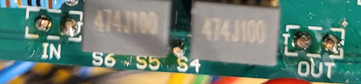
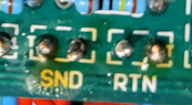
October 30, 2025 at 11:56 am #37755BarryKeymasterOn the IN and OUT pads be sure to verify that the Pad with the T in each group is your audio path and the Pad beside it is the ground. For the IN grouping the T pad is on the right and the OUT the T pad is on the left.
The same then applies to the Send and Return groupings.
Be sure that the Pad with the T is your audio path as the other is ground.
Beyond that I would be verifying all connections with a DMM for continuity including common ground and finally an Audio Probe.
October 30, 2025 at 12:40 pm #37756brdModeratorSorry I didn’t think of it earlier, you could also try connecting the wet and dry sends to the amp. If you get sound, the problem is in the last half of the circuit then. Also be sure the Volume pots are fully clockwise when using the normal output jack, those are more like blend controls.
The box looks awesome BTW. I have one of my paramix’s in the same enclosure.
November 3, 2025 at 5:01 pm #37794JohnnysmokeParticipantThanks for the compliment! I tried all sends and all returns to the amp. I’ve also tried connecting my ‘in’ to the returns with the ‘out’ to the amp. Volume pots are turned fully clockwise.
Nada. Not even a hiss. Nothing.As per Barry’s post, I also went over the in/out jacks wiring, actually ALL of the wiring, probably 30 times by now. Tips and grounds are all in their prospective pads, I’ve quadruple checked those pesky switched jacks, too.
I’m about at wits end. Tomorrow I’ll finally have some time to make an audio probe, although I’m not sure what to do with it. As per Barry’s suggestion, I guess I’ll learn how to DMM some things, too. This has been a long time coming, I guess it is time to learn what I’m actually doing.
ODD: I was messing with the guts on this thing, and the power LED to the foot switch light up NICE AND BRIGHT when the ground on it touched the pedal housing. I didn’t know it before…but I guess that the LED is very DIM – the led on the kill switch is nice and bright, though. I had the power LED inside a Fender-style “jewel” button, so I thought that was the reason it was so dim.
November 4, 2025 at 9:37 am #37801PlaysforfunModerator“Nothing out of the output jack, either. Does not matter if the foot switch is engaged, or isn’t.”
So you don’t have ‘bypass’ but the led works. Something silly is happening. Don’t fret yet.
“I’m not an electronics expert by any means so checking resistances and/or pinouts on the opamp are a bit out of my league”
You say you’ve checked resistances. Does the meter check continuity? Because you have some checking to do.
“I’ve completely taken everything out of the enclosure, and gone over the PCB with a fine-tool comb looking for soldering bridges, wires in the wrong places, etc.”
Your pictures say otherwise and haven’t been useful so far. If you want to give us good and totally in focus pictures, you will have to remove it completely and spread it out so we can follow wires, even though you have done it 30 times. What is your color code?
“The LEDs for the foot switch and kill switch work and light up correctly.”
Let’s take a moment to count our blessings. Two.
“I was wondering if the TL074 might be suspect”
Seems like it. An audio probe would give most of the answer. Find a ‘good’ TL074 from another pedal, perhaps, and swap it in. Check for bent legs (pins).
“I’ve had to restrain myself from throwing it in the bin a few times…”
Don’t do that. The board looks plenty fine. I would be tempted to de-solder and clean all jacks. Then install the jacks into the closure and solder them properly while in place after you trimmed the excess wire. Neatness isn’t art. It’s just smart. But that’s just me.
“I’ll use the Barry’s Hookup wire I have on hand.”
Then order more or 24 gauge pre-tinned. I prefer stranded but solid works too.
“Also posted IC voltages. Thank you!”
Some. But a full accounting would be better. Here are mine:
Input voltage 8.75 vdc
1: 4.37 14: 4.37
2: 4.37 13: 4.37
3: 4.37 12: 3.98
4: 8.74 11: 0.00
5: 4.36 10: 3.98
6: 4.36 9: 4.37
7: 4.36 8: 4.37
All my troubleshooting leads and wires are in excellent condition, kept separate, and proven to work prior to troubleshooting.
I have ground continuity everywhere I should according to the schematic using my DMM.
I have ‘bypass’ through my in and out jacks and ‘power switch’ when Paramix is inactive.
If your success rate is as you say then you are way better than me. Mistakes with all this wiring are easy to make. Since you have done the T-Ditty Boost mod, you are aware of the v4.5 build document. Directly after the mod, starts the additional troubleshooting points from Tonmann. He is awesome. Complete that guide as laid out and you will be well off. Follow it up with an audio probe after reinstalling the chip. We can help. But you actually have to have one. So simple to make. It doesn’t need to be fancy. A guitar cord, a wire and a capacitor will get you there. Let us know when you are ready to proceed. We can walk you through it systematically.
November 4, 2025 at 6:27 pm #37804JohnnysmokeParticipantJust spent a couple more hours on this. Numbers are:
Input voltage 9.46 vdc
1: 4.69 14: 4.69
2: 4.69 13: 4.69
3: 4.69 12: 4.69
4: 9.46 11: 0.00
5: 4.69 10: 4.26
6: 4.70 9: 4.69
7: 4.70 8: 4.69
I built a sound probe today. Nifty device. And it gave me an even more puzzling result. (puzzling to me, anyway, LOL)
The instrument cable going into the “IN” jack produces sound at the tip of the cable, if the switch is OFF. Normal, right? I mean, who doesn’t expect that. LOL. However…
When the switch is ON, there is no more incoming sound, not even at the tip of the instrument cable that is plugged into the “IN” jack. (!)
There is sound at the incoming terminal on the footswitch only if it is OFF (which makes sense that the same holds true for the tip of the instrument cable going into the IN jack, I suppose…that’s pretty much a direct line from the instrument cable tip to the incoming footswitch terminal via a wire).
I took the footswitch apart, nothing suspicious. I cleaned the parts a bit hoping maybe the grease was causing some connectivity issues then I put the footswitch back together: Still the same behavior.
I again checked to make sure the jacks, footswitch, etc., are connected properly, all wiring is where it should be. Checked and re-flowed some soldier here and there: Still the same behavior.
Earlier I had recanted my statement about my “power on” LED – it is dull. I touched the ground wire of the LED to a ground while the footswitch was “ON” and it lit up brightly. Removing the additional ‘test’ ground connection that I had added results in the LED going dull again.
Tomorrow I will break out the DMM and see if I can figure out how to measure things as per the Tonman section of the instructions…I also have a capacitance tester…dunno if that will help me but I’ll try to figure this out some more tomorrow.
BTW: I have two ICs, same results with both of them, swapping them did not help (but I did not take one from a ‘working’ pedal)
Will continue tomorrow. Sigh.
Thanks for help/tips/ideas
November 4, 2025 at 11:33 pm #37808JohnnysmokeParticipantI just barely drifted off to sleep, and I bolt upright with an idea that pops into my head: is the orientation of the foot switch wrong?
Did I just have my ‘Euteka’ moment?
I think have the lugs perpendicular instead of horizontal. I’ll not be able to sleep until I can sneak out and peek at my pedal.
I was reminiscing about how the inner works of the foot switch operated, the three metal pieces only able to rock back/forth in a certain direction, therefore the orientation of the switch…I think should have been turned 90 degrees. Oh jeez, I’ll never get any sleep now!!!
November 5, 2025 at 7:29 am #37809PlaysforfunModeratorThat would make sense since the input seems to go to ground. Switch lugs should have a horizontal position as the works of the switch are in vertical columns. For everyone else reading this, please go make an audio probe. Take Johnnysmoke’s word for it. It’s nifty.
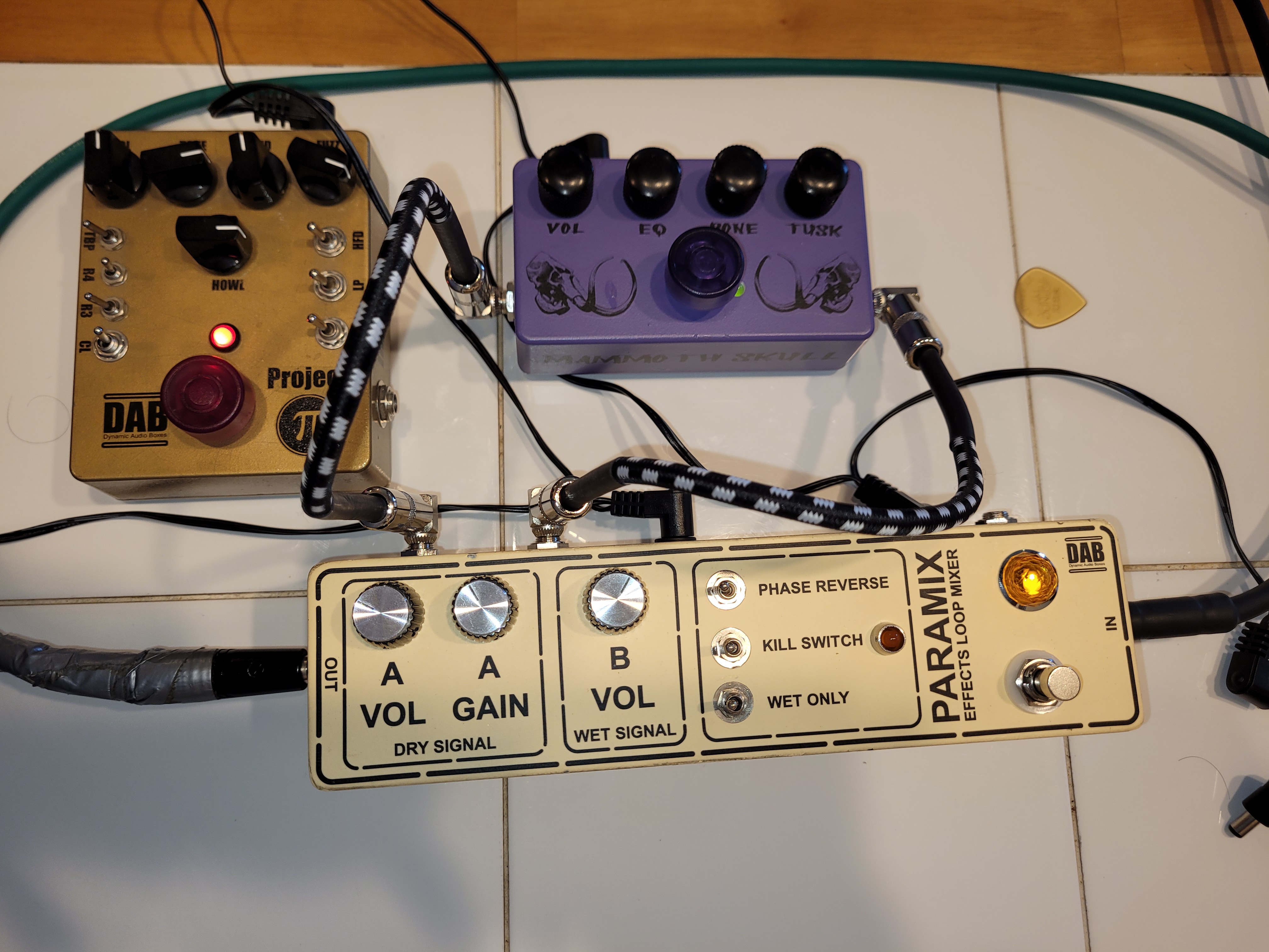
November 5, 2025 at 1:18 pm #37813JohnnysmokeParticipantIt lives. Got a new footswitch, wired it in CORRECTLY – and I’ve been messing around with the Paramix for over an hour now, testing the few pedals I have at our apartment. Can’t wait to bring it home tomorrow, I really want to run my Rat Deluxe build in parallel with some other builds.
Also in the pic, a couple other GuitarPCB pedals I put together back in 2014.
-
AuthorPosts


- You must be logged in to reply to this topic.