@barry
Forum Replies Created
-
AuthorPosts
-
 BarryKeymaster
I love that!
Thanks for sharing.
BarryKeymasterThe builds are nearly identical aside from the added potentiometer.
BarryKeymasterHopefully that takes care of it.
BarryKeymasterI am only guessing here but if you are referring to 1991 (Pearl Jam) which has two Gains this is the schematic from that build document.
Both Build documents are available on the Guides Page:
BarryKeymasterWhich Funny Little Boxes?
1991 or DIRT.
Keep in mind I am not the designer and they only come with what is provided but all of them have been built by someone.
If it is DIRT someone on the forum as I recall has built that one so you could look at theirs for help using the search.
Direct Link: https://guitarpcb.com/community/topic/dirt/
BarryKeymasterWonderful! Love it!
The Mule Kicks! I am glad you agree.
BarryKeymasterVery nice! It’s a winning pair.
Thanks for sharing.
BarryKeymasterHow do you like the values chosen for the Stock / Bass cut mod?
BarryKeymasterLooks like one of my local Boyer Mallo Cups sitting on a Christmas package.
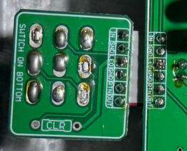
BarryKeymasterI would suggest using some liquid solder FLUX when reflowing along with your solder.
There are many cold solder joints. Also be careful of the iron temperature.
Finally be sure you are using a fine conical tip when doing the small pads above the switch as some of them look like cold joints or limited solder.
For the larger switch pads place a small drop of flux on each pad and reflow the solder. You will not be able to force the switch in any closer but as long as you make a good solder connection you will be fine.
I always apply FLUX to switch lugs before soldering them to PCBs. It just makes everything better.
Most importantly, take your time, and be careful not to burn any solder pads or you will likely need a new PCB.
BarryKeymasterVery nice, and thanks for sharing.
I love this circuit!
BarryKeymasterI just now saw your post about capacitor code.
Edit; I just did a double-look.
Edit 2: Yah double look there too. 470pF
Use Google or find a chart to use if you are unsure about the code
BarryKeymasterI can’t really trace anything from those photos — there are just too many wires and connections to pinpoint the issue visually.
What I recommend is this:
-
Verify the SD9 circuit works on its own before attaching it to the Afterblaster board. Break the system down and test each part separately. That’s the fastest way to narrow down and reveal the problem.
-
Check all ground connections carefully. Use your DMM in continuity mode and make sure every required common ground point is actually connected. A missing or floating ground is one of the most common causes of high-pitch squealing.
With this many wires and add-ons, the problem could be several things — but I would start with isolating the SD9 and confirming proper grounding throughout the build. That should point you in the right direction.
BarryKeymasterYep another great one!
Excellent work and thanks for sharing.
BarryKeymasterSorry for the issue with the populated board image in the build document. I’ve removed that image. That was a very old and, in hindsight, bad idea — laying little resistor images on the PCB one at a time (as if you were soldering them) made it far too easy to introduce a photo typo. I stopped doing it a long time ago, but I missed this one.
This all happened while I was recovering from a stroke, and the image exercise was actually meant to help me regain my vision. While I always recommend following the BOM and schematic when building, I completely understand the temptation to use the photo. Thanks for catching it!
BarryKeymasterVery nice and thanks for sharing.
I will have to add that to the build document.Yes, the resistor value change is key to making the math work on the Mod.
BarryKeymasterExcellent looking build.
Thanks for sharing.
-
-
AuthorPosts