@barry
Forum Replies Created
-
AuthorPosts
-
 BarryKeymaster
Another Dual Channel Pedal
Dual Channel MoRC Compressor below Courtesy of J Allen Shaw
BarryKeymasterNo jumpering they just fit right in if needed. Just do not install the LEDs.
I would use LEDs as one of my choices though!
BarryKeymasterSince it does not work in Bypass mode that means the wiring is not correct between the Jacks and Footswitch because Bypass means the main circuit board is bypassed entirely. Please follow the Wiring Guide I placed above for you.
BarryKeymasterMore Dual Channel pedals.
Dual Channel MKC and EA Tremolo below Courtesy of J Allen Shaw
BarryKeymasterMOUSER <- Click
Go to the MLCC section (link above) and pick from the drop down windows the Termination type which is Radial and the Capacitance which is 2.2uF in this case and then hit Apply Filter.
Once you scroll down there are many choices. Just make sure they have a 5mm lead spread.
BarryKeymasterMy best guess is that you have the same wiring problem with both pedals but I cannot see the wiring job in the photo above clearly enough to be able to help. The wires are same color and running side by side. I cannot follow the wiring or check all common grounding.
We will need much better photos or a diagram to clearly show the wiring.
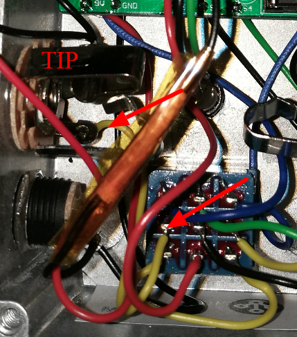
Foot switch Lug 2 (I) Looks like it is going to Shield instead of the Jack Tip but I cannot see it good enough to be sure.
Because it is likely the same error it would be easier to work on one pedal for now.
Also did you look at the GUIDES PAGE to trace the wiring yourself?
Does the pedal work in bypass mode?
Also check these guides from the GUIDES PAGE and make sure the wiring is correct and you have checked the entire circuit for proper continuity using your digital multi meter.
BarryKeymasterI am not sure if anyone speaks German here. The LED needs connected to the foot switch to work.
I cannot verify any off-board wiring as it is mixed too close with wires of the same color.
My first guess is the the wiring is wrong somewhere (on both builds) but it is too hard to see from the one photo above. I cannot follow the wiring or check all common grounding.
We will need better photos or a diagram to show exactly how it is wired.
Since you wired the LED to the MAIN Board and not the 3PDT Wiring board it still needs a S3, S4 & S5 connection. You will have to make contact over top the wiring board after you figure the Audio issue.
Since both builds do not work it is likely the same error and it would be easier to work on one pedal.
Also did you look at the GUIDES PAGE to trace the wiring yourself?
Does the pedal work in bypass mode?
Also check these guides from the GUIDES PAGE and make sure the wiring is correct and you have checked the entire circuit for proper continuity using your digital multi meter.
BarryKeymasterHere is something to think about:
Dual Channel MoRC Compressor
Dual Channel Zenith
Make any pedal a dual pedal. Here is the Dual D’Lay courtesy of J Allen Shaw
BarryKeymasterTo be clear you still need an amplifier.
We do not comment on amplifiers due to the fact that there are many beginners who do not understand the dangers but that said there are a ton of cheap DIY kits or commercially built solutions to be googled. Most of the cheaper DIY versions use the LM386 and are based on the Ruby Amp
BarryKeymasterJust a friendly reminder before starting a build to always RTFM on the Guides Page
Oh and orange typically means there is a link to click.
BarryKeymasterAlso have you done the battery test while only using the Sunn-T by itself with no other circuits hooked up?
Batteries cannot produce noise and by doing the battery test while only using 1 pedal and 2 good cables you will rule out about 15 possible problems that would have to do with power supply.
BarryKeymasterIf you have noise there is likely another issue but I cannot be sure without testing all transistors first.
They need to all read 4.5v to 5v.
If you get that accomplished and still have undesirable noise I would start check and re-flowing all common grounds both on and off board as well as using an audio probe if that does not work out to more easily find the offending area.
My circuit does not make undesirable noise and in the year we have been selling them it has never been mentioned as an issue so start with transistors then re-flow common grounds and finally check the entire audio path with an audio probe.
BarryKeymasterYou need to refocus on biasing. If you are running one too high (6v & up) you will induce noise. Half the supply voltage is what you are looking for at optimal settings.
It would be much more helpful if we knew the exact voltages on all transistors by number.
Also it is always helpful to place a photo in the working thread if there is something we need to see so we are not trying to jump back and forth between threads.
Additionally since the project is designed to emulate an overdriven Sunn type amplifier it will not completely clean up unless you lower the volume on your guitar. (Your guitar pickups are always part of every circuit). We are not emulating the power section of the amp and only the preamp section which is desired for its clipping characteristics.
Hopefully you socketed your transistors so you can carefully try them in different locations in an effort to get the bias better because no transistor is identical even from the same plant on the same day.
BarryKeymasterWe have a Guides Page which cover these type of questions with diagrams.
Here is the direct link to the Guides Page.
For a specific answer (although I do hope you check out our guides before building) foot switch orientation only matters in two of the four ways available to you. As for the two good ways it does not matter. Now go to page 5 of the Crash Course Guide which is found on the Guides Page. The two bad ways would just not make visible sense when looking at our guides as the solder lugs would be wrong.
Also note when you go to the Guides Page you will see a drawing diagram of how to wire the foot switch in its basic form as well although I would still read Page 5 of the Crash Course and probably the rest of it.
That should help tremendously and I also suggest the Beginners Guide also on the Guides Page.
Also the Soldering Tutorial video for GPCB boards on the Guides Page.
It can be accessed any time from our Home Page or the Forum Home Page for future reference.
BarryKeymasterSince you are new, new I would state that RTFM is what we lovingly refer to as Read The Fantastic Manuals. The main build document aside you can also learn a ton from our RTFM pages also known as the Guides Pages which I am certain you will find helpful.
You will even see a diagram showing how to wire a DPDT board with examples but also check out all the PDF Guides up top as well.
BarryKeymasterWe always suggest 24 gauge wire for pedals
That is what Barry’s Best wire is which sells like crazy when I have it. It is also pre-tinned. Since Klaus does not carry my wire because it is hard for me to get I am certain another brand of 24 Gauge may be available.
I will have to talk to Klaus about supplying 22 gauge as that is heavier than we use. 22 Gauge will work considering it is smaller in diameter than a 1N4001 diode (which easily fits our pads) so we know it works but it is a bit more difficult. 24 Gauge is the common we like and I suggest using that if you can.
See our Slide Show Main Menu Bar for lots of examples.
Also see the Combo Build Guide for more examples of using 24 Gauge.
Also please know I do not get commission and I am not involved in any way with the kit process. I only provide Klaus with circuit boards and nothing more so I do not have a lot of say.
Perhaps he can send you 24 Gauge upon request?
BarryKeymasterI discovered some of those not too long ago myself I think I got them from Bitches love my Switches and I like them with the wiring boards as well and that minor modification is quite easy to do.
All together it makes for an extremely robust foot switch.
-
AuthorPosts