@barry
Forum Replies Created
-
AuthorPosts
-
 BarryKeymaster
Here is a screengrab from the build doc. Essentially you have two options for a status LED. You can either use a Common Anode Bi-color LED (D1) or use two different color standard LEDs. (DA & DB)
This is purely for aesthetics on how you want your finished pedal to look.
See image below:
This is also referred in the schematic as well by the diode symbols. We suggest looking at schematic even if you are new to them as things will become very familiar, very quickly and that’s always a bonus.
BarryKeymasterWell Done Billy!
BarryKeymasterBoth the 3PDT Toggle version and the 4PDT version w/ LED are available in a limited supply. There are also 4PDT foot switches available as well for the 4PDT version. The foot switches are only available in the US due to thickness.
BarryKeymasterOur Easy Order Switching boards take combo builds to the next level.
So much versatility in a compact pedal. Thanks for sharing.
BarryKeymasterNicely done. I occasionally use Vero for a circuit trial, modifications or testing mods.
Using a breadboard is a common tool for testing circuits and also has noise involved for obvious reasons but realizing that is to be expected eliminates most concern.
Noise beyond that like you describe can be due to how the board is laid out with components in proximity to other components that should not be. Our circuit boards are always carefully designed to avoid this and in some cases we will create a separate ground plane to completely isolate the components from each other above an beyond what you will see boutique or even commercial companies do.
BarryKeymasterThere is no technical name for the switching options.
It is based on what you think it sounds like. This is subjective to many different builders as you will often hear words like Tube-like sound etc.. This is what many commercial people do or you could just say LED, Silicon etc… or just leave the switching blank or with symbols of some kind.
There is a clipping chart in the build document that describes the switching:
I personally would not want to tackle assigning names to all of that but if you come up with something be sure to share with us. More often than not i suspect a Guitarist will flip switches till they hear exactly what they like and leave it there. Maybe when switching guitars or music style they might prefer another option.
BarryKeymasterThat could be a serious Box Of Doom if one were so inclined to play in that style.
BarryKeymasterNice Art.
Thanks for sharing and be sure to upload your DSOTM pedal in the Show Off section.
BarryKeymasterI can say that something is a miss but I would be looking at everything.
Take voltages with the Speed pot down and the Depth pot full up because of the LFO. I would be curious where your 2N5457s came from because good ones are very difficult to find these days. I agree with what Billy said.
BarryKeymasterWell done and looks great. I like the acrylic bottom.
What I want to know is how does it sound after having played it for a while?
BarryKeymasterThe Crash Course Guide on the Guides Page will show how to take voltages.
BarryKeymasterWelcome on board!
R1 (1k) must be installed. This creates a break in the circuit. See schematic for visual.
The wiring job looks great!
BarryKeymasterDo you have bypass signal?
If you do not have Bypass Signal then it is still wired wrong.
It is very hard for me to help since I cannot see what I need with the two pictures provided.
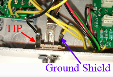
Did you fix this Output Jack?
Since the Output Jack was wired incorrectly the Input Jack may likely be wrong as well.
You will need to verify the Input Jack.
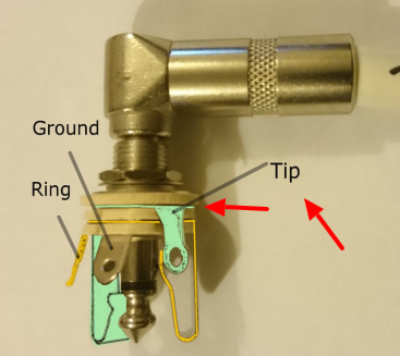
The Tip and The Ring are not always exactly the same on every brand of Jack. You must look closely at the connection on the side of the JACK.
This is very hard for me to judge with my limited visibility of your project.
BarryKeymasterIt may be a while till Musikding carries the Tube Screaming Preamp as a kit because it is new and i have to ship him the boards from the USA.
As for connectors to poteniometer pads with the smaller pad we refer to those as Pin Headers.
I do not really care for them myself but I have seen others use them.
You must have a 2.54mm or 0.1″ spacing for them to fit either the potentiometer pads or the T&S Pads on the Input and Output. Here is a LINK for an example.
They make them in two wire, 3 wire (seen above) and other forms. The 2.54mm or 0.1″ size is important.
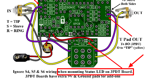
BarryKeymasterRight since you have no resistor you will have to carefully tack solder the 3 wires then and connect them to the 3PDT Wiring board as illustrated. Also to avoid confusion you already used the CLR resistor on the Main Board. The reason the wire for S4, S5 and S6 are not shown on your diagram is because you did not use the 3PDT Wiring Board for your LED.
Because you mount the LED to the Main Board you have to do this!
To fully understand different builders like to do things in different ways. Our boards are designed to accomodate different builders. The hard part I guess when you are new is to learn what works best for you. After that you will know how you like to build and it is always the same.
Finally one more time you do not need to worry about the Audio Path until you fix the Bypass switching. Once you have Bypass Audio then you may not have to do anything else after that.
BarryKeymaster“Also zusätzlich zum D2 die ich schon angelötet habe muss ich noch die S4, 5,6 mit verbinden, richtig?”
Yes because you did not hook the LED to the 3PDT Wiring Board.
The foot switch is what tells the pedal if it is On or Off. Since there is no LED on the Foot switch then you have to make the wire connection or wire and LED to the foot switch. If you wire an LED to the foot switch do not forget the CLR first (Current Limiting Resistor) anything from 2k to 4k7 will do.
I still cannot follow the wiring. You will need to manually make sure all connections are correct especially regarding the Input and Output Jacks. If there is no sound in Bypass Mode then it is wired wrong.
BarryKeymasterI could answer these questions however I know that Wilkie (who is currently on Vacation) has been working on ideas like this for some of his clients in Colorado. I think it would be best to allow him to put his thoughts to this when he gets back. There are a few sorta yes and maybe not answers to some of the questions and much is certainly subjective and there may be ideas you have not yet thought of.
I would prefer to wait for Wilkies input based on some of the projects he has recently been working on that we have been discussing and I certainly do not want to steal any of that thunder.
-
AuthorPosts