
Your Source for DIY Pedal PCBs and NostalgiTone! › GuitarPCB Forum › GuitarPCB Build Support › Mini-ME funktioniert nicht
- This topic has 5 replies, 3 voices, and was last updated 7 years, 6 months ago by
 Barry.

-
AuthorPosts
-
March 6, 2019 at 2:26 pm #4591AnonymousInactive
Hallo, leider funktioniert mein mini me nicht.
Das LED lechtet aber es kommt kein Signal.
Kann mir jemand helfen?
Gruss Chris
March 6, 2019 at 3:59 pm #4594BarryKeymasterMy best guess is that you have the same wiring problem with both pedals but I cannot see the wiring job in the photo above clearly enough to be able to help. The wires are same color and running side by side. I cannot follow the wiring or check all common grounding.
We will need much better photos or a diagram to clearly show the wiring.
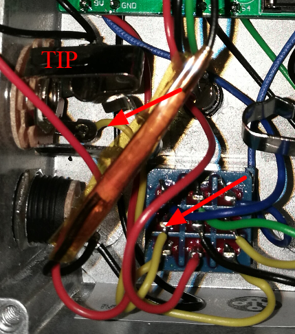
Foot switch Lug 2 (I) Looks like it is going to Shield instead of the Jack Tip but I cannot see it good enough to be sure.
Because it is likely the same error it would be easier to work on one pedal for now.
Also did you look at the GUIDES PAGE to trace the wiring yourself?
Does the pedal work in bypass mode?
Also check these guides from the GUIDES PAGE and make sure the wiring is correct and you have checked the entire circuit for proper continuity using your digital multi meter.
March 7, 2019 at 1:52 pm #4615CybercowParticipantWie bei dem anderen Pedalproblem, das Sie gepostet haben, schlage ich vor, Ihre Verdrahtung zu überprüfen. Leider zeigt das mitgelieferte Foto nicht genügend Kabelverbindungen. Es wäre auch gut, die Unterseite der Leiterplatte zu sehen – es würde uns die In \ Out-Anschlüsse der Leiterplatte anzeigen lassen. (Google Translate)
As in the other pedal problem you posted, I suggest double-checking your wiring. Unfortunately, the supplied photo does not show enough of the wiring connections. Seeing the underside of the PCB would be good too – it would let us see the PCB’s In\Out connection points.
March 9, 2019 at 4:23 am #4645AnonymousInactiveDanke für Ihre Antwort, habe den Fehler noch nicht gefunden. Im Bypass Modus funktioniert er auch nicht
Sehen Sie hier mehr?
March 9, 2019 at 7:22 am #4646CybercowParticipantWir müssen in der Lage sein, alle Anschlüsse auf der Platine, die Buchsen und den Stomp-Schalter klar zu sehen. Sobald wir alle diese Verbindungen im Überblick haben, können wir Ihnen möglicherweise dabei helfen, das Problem zu finden. Haben Sie Ihre Arbeit anhand der von Barry zur Verfügung gestellten Bilder überprüft? (Google Translate)
We need to be able to clearly see all the connections on the PCB, the jacks and the stomp switch. Once we have a clear view of all those connections, we might be able to help you find the problem. Did you double check your work against the instruction pictures Barry provided?
March 9, 2019 at 9:45 am #4647BarryKeymasterSince it does not work in Bypass mode that means the wiring is not correct between the Jacks and Footswitch because Bypass means the main circuit board is bypassed entirely. Please follow the Wiring Guide I placed above for you.
-
AuthorPosts






- You must be logged in to reply to this topic.