@barry
Forum Replies Created
-
AuthorPosts
-
 BarryKeymaster
Click on the GUIDES PAGE link above at the top of the page in the Main Menu Bar.
Then scroll down to look at all of the examples.
BarryKeymasterThere are a lot of potential problems for pedal popping.
The type of pop can be different as well leading to the issue.
Here is just one thing I found using this Google Link
BarryKeymasterEither way is fine but I would use it at the output of the MoRC myself.
BarryKeymasterBuild doc updated.
At a glance I believe this circuit inverts the phase? If so you would need a small circuit like the 1″ x 1″ Stage 3 Booster to correct the phase.
BarryKeymasterVery nice Shane and agreed on wire dressing. MXR started that trend in the 70’s which brought pedal size down to fit in the hand size. I also like the hand written letters a lot.
I bet that would be a super versatile monster with an Easy Order switching board 😉
BarryKeymasterWell done and thanks for sharing!
What is scarier than the Great White?
BarryKeymasterGlad you are liking some of the other builds.
The Phase has a higher output impedance than others. This is typically not an issue. I assume you tried a pedal with a buffer directly after it and that it improved the situation?
Wilkie1 also previously asked “If you bypass the Wampler and send the Dr. Phybes signal directly into the Moor, do you have a signal loss?”
Knowing some of this added info might help.
Anyway my preference with this circuit is always pre-distortion. I really do not like it post distortion but that is perhaps because I like Pink Floyd, Robin Trower and that type of Phase sound. That said if you determine it is killing your volume and that by placing a buffered pedal after it solves these issues then I can understand what you are going for.
Thanks
BarryKeymasterI would re-flow solder joints on most of the project.
There are a couple places that look like there is not much wire holding onto the pad or solder bulbs that are likely a cold joint. Also re-flow the 3PDT pads so the joints flow. Just heat your iron up using a fine conical tip and flip the board over to the back and do all the joints. Then pay close attention to any wiring issues. Especially any wires hanging by a thread would need redone.
Here are a couple places I can see from the photo.
If you still have trouble when you are done with that upload new photos and include as much of the back side of the board as you can with the pots angled up. I would suggest .031 diameter solder if you have it as it will help make a quick, solid solder joint.
BarryKeymasterEagle Eyes!!
BarryKeymasterVery nice and thanks for sharing!!
Can you take a voltage reading for the Drain leg of each Q of the Diamond Drive and report? Sounds like it is running a hot Bias.
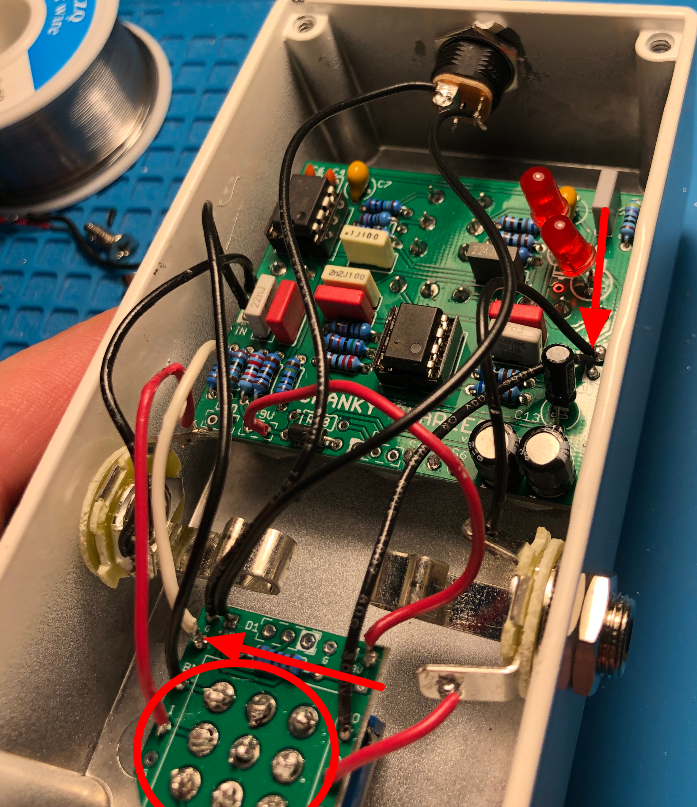
BarryKeymasterThe only thing different between the new and old diagram is the the Tip and Ring lugs were switched on a stereo Jack and you are using a Mono jack and no battery so that would not have been a major issue. So what you need to look for is some sort of short. I would look hard at the connection on the IN side and be sure there is not a stray wire touching ground since they are so close together.
Also:
BarryKeymasterBuild document has been updated and sorry for any confusion.
Thanks though for pointing it out so I could correct the error in the Build Document.
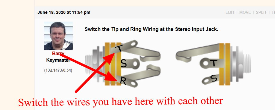
BarryKeymasterSwitch the Tip and Ring Wiring at the Stereo Input Jack.
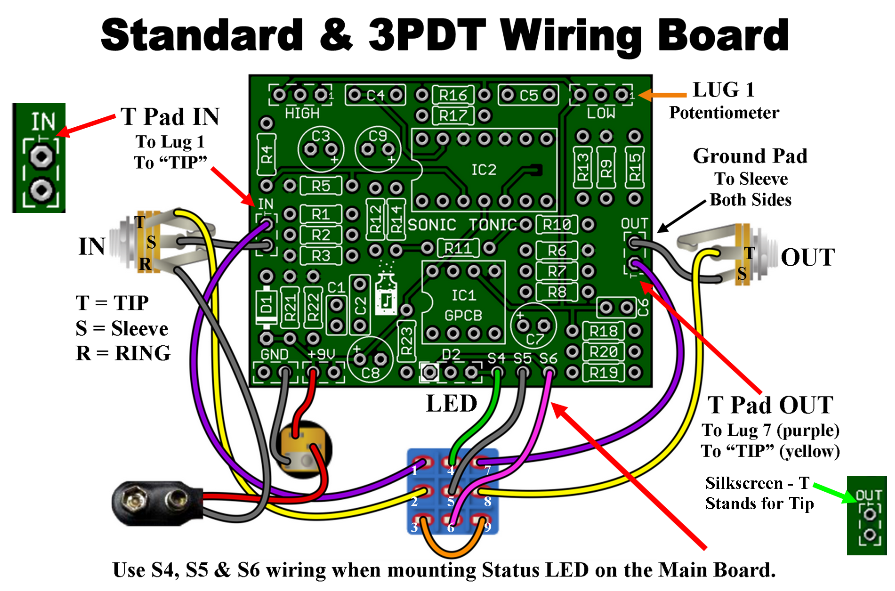
Updated wiring diagram
BarryKeymasterYou might try a GBOF Meat Fuzz or perhaps go PNP Germanium with Bias or create your own with a GBOF board. That said so people know what we are talking about here is an image.
Any info I find appear to be educated guesses. Lots of Heathkit TA-28 references.
There is some info here that sounds about right:
I would think a cheap early fuzz like the TA-28 with that particular type of guitar playing through a breaking up amp should be damn close. I think this is also a good reason for the tone of his Wah Wah stuff.
TA-28 Video for reference.
For other peoples reference here is a video that shows his base tone and then the Fuzz he uses for solos.
BarryKeymasterI would ask for them to send you a GPCB wiring board so you can do what you want more easily.
No, you cannot wire a Bi-Color LED to that although you could wire the LED to the Main Board.
I hope that helps. I would still let them know about the error and why.
BarryKeymasterThe first thing I would do is a solid re-flow of everything in that area of the circuit including making sure transistors are properly seated as well. Flip it over and work the back of the board and re-flow all solder joints
BarryKeymasterThat was an excellent circuit analysis. I appreciate the effort that went into making that.
I should point out that when I say Tonmann is “no longer with us” I mean to say he disappeared without a trace and we would all certainly hope that it is not because he passed away but maybe moved or something. At any rate we do not know exactly what his whereabouts are and we all certainly miss him.
Send me a message so I can send you something.
-
AuthorPosts