@barry
Forum Replies Created
-
AuthorPosts
-
 BarryKeymaster
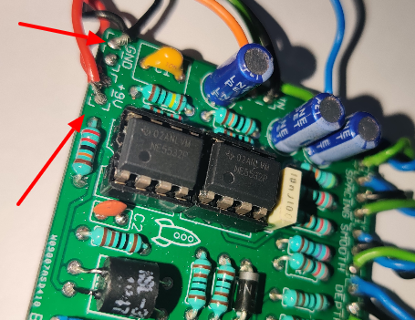
That is an old wiring board. We have upgraded the wiring boards to have symmetrical pairs of 9v / Ground connections placed on either side of the boards as opposed to just way too many grounds. I am still going through the old build documents and updating those that happen to have that particular diagram first.
BarryKeymasterWow 5 left. I guess I need to get more quick.
I appreciate the business through these difficult times. Thank you!
BarryKeymasterFor reference. I just made this up for the updated 2020 Build Document.
BarryKeymasterSince what you described sounded like unbiased transistors and since your bias did not help I agree that would be my next step. As Wilkie says remove the transistors so as not to heat them up and take your iron tip and touch each joint and re-flow the solder. This will insure you have a great solder joint at every location.
I would mark each transistor with some tape so you can put it back in its previously tested space. Then be sure to re-bias again.
BarryKeymasterExcellent! I hope you feel that troubleshooting in its own way can also be a rewarding experience.
BarryKeymasterYour audio test should have greatly improved after biasing, what are the results?
Make sure all potentiometers are at about half way point.
BarryKeymasterYou need to go and re-bias all the transistors now starting with Q1 and work down the line. Make sure that you are using the correct trimmer for the transistor. Report your voltages.
BarryKeymasterYes either version is correct as they are both accomplishing the same thing.
Potentiometers are variable resistors. They must be connected.
The black plastic box makes it nice to see what would go where.
BarryKeymasteror better just reconnect the off-board wiring and hook it up to the Beavis Board and take a good photo of that. You are going to need to reconnect it anyway to take voltages and you will need to reconnect all of those pots.
BarryKeymasterI would really like to rule out the wiring some how as that is the most likely culprit and everything else that is less likely will take a while.
Maybe draw me how you connected it to the beavis box which would be easier in that case. You can even hand draw it for me and take a photo of that.
BTW be sure your Voltage Sag on the beavis box didn’t get bumped.
BarryKeymasterHi and welcome!
Usually when you have a no sound issue it is an error in the off-board wiring.
I don’t suppose you have any photos of that lying around?
BarryKeymasterAs Mark said they are two separate locations. So if you look at the schematic (even if you don’t read schematics) the basic takeaway is that they are separate. Follow the instructions for the Mod at D5 and populate D1 and D2 as normal.
Here is what I am referring to so you can get a visual:
BarryKeymasterD5
BarryKeymasterD’Lay Tap Tempo Doc added to Master List on Guides Page.
Here is an image for Resistor color bands (not considering mods) as well as orientation sensitive components.
Zoom in if needed.
I hope that helps.
BarryKeymasterI have had something like this happen before and it was due to wiring that was stressed or broken as well as a bad solder joint. I did not even realize till the wire got crippled and was about to fall off. I always make sure I put the wiring in far enough to place the pvc flush with the edge of the board and that has not happened since although I still always check that out of habit when trouble shooting.
While this one small section may not be your exact problem it is an example of what I am talking about below.
I would check all of board wiring and grounds again and tidy up any suspicious sections.
BarryKeymasterThe code for the trimpot should be 104. 10 and 4 zeros for 100,000 or 100k.
Sounds like you may have a 102 which would be 10 and 2 zeros for 1000 or 1k.
There is no way it would work if that were the case since the preferable setting would be near half rotation or about 1:00.
BarryKeymasterI will take care of the R10 copy and paste typo as it should be the CLR at R34.
-
AuthorPosts