Your Source for DIY Pedal PCBs and NostalgiTone! › GuitarPCB Forum › GuitarPCB Build Support › NostalgiTone NT Phaser V1
- This topic has 15 replies, 4 voices, and was last updated 1 month, 1 week ago by
 Barry.
-
AuthorPosts
-
April 25, 2026 at 4:11 am #38952Vokinn72Participant
Hi All,
So I’ve got the kit from PedalParts which came with a schematic and I downloaded the info with the drill templates.
This is the first pedal build I’ve ever done. In fact this is only the 2nd PCB that I have ever done and although there is a tonne of info on YouTube etc for how to read schematics etc I’m curious if there is any more info on how to build this thing for total newbies. I really want to get into building pedals. I built a $20 PCB kit and loved it. Just want a little more direction or help with this build as I don’t want to stuff it up. Any info or help or advice would be greatly appreciated. I’ve been looking at the pedals on here and they all look awesome! I wanna be able to make them as well.
Thanks,
Nik.
April 25, 2026 at 5:45 pm #38953BarryKeymasterHi and welcome.
There are several beginner guides on the Guides Page.
You can access through the Main Menu Bar up top or:
Scroll down and find the tings you need and take your time.
April 25, 2026 at 7:02 pm #38954Vokinn72ParticipantThanks again Barry!
April 25, 2026 at 11:35 pm #38957JasonWickershamParticipantVokinn52, welcome!
I have a thing for optical phasers, and this one is great! The faceplate is a cool touch if you decide to add it as well.Ask away with any questions.
April 25, 2026 at 11:39 pm #38958Vokinn72ParticipantAwesome! Appreciate any help!
Like I said it’s my first build (aside from a $20 kit I bought to practice soldering). I’ve been procrastinating with starting because I don’t want to screw it up but have also been watching a TONNE of YouTube videos so think I have the basics down now.
One question I have straight up is the kit I built had a line on the PCB to indicate which way to solder the resistors. This one doesn’t. Is this indicated on the schematic?
April 26, 2026 at 4:18 am #38959Vokinn72ParticipantSorry, I meant diodes not resistors.
April 26, 2026 at 6:42 am #38960brdParticipantVokinn72
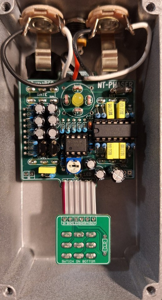
Welcome to the exciting journey that is pedal building. I’m not one of the gurus here but I try to help where I can. As for your question about the diodes. the build doc has a picture of the board that I’m using for reference. there are only 2 diodes in the build. D1 is an LED, D2 is a 1N5817. The printing on the board sometimes has a circle with a flat spot to help orientate an LED, this one just has a plus and minus sign. here is a picture to help you.
The LED has a flat spot. The positive side is the Anode, the negative side is the Cathode.D2 should be installed as shown in the build doc in the upper right corner. The cathode should be to the right.
As far as tips to get started.
- First read the beginners guides Barry mentioned.
- Read the build doc. There are usually build notes for important information.
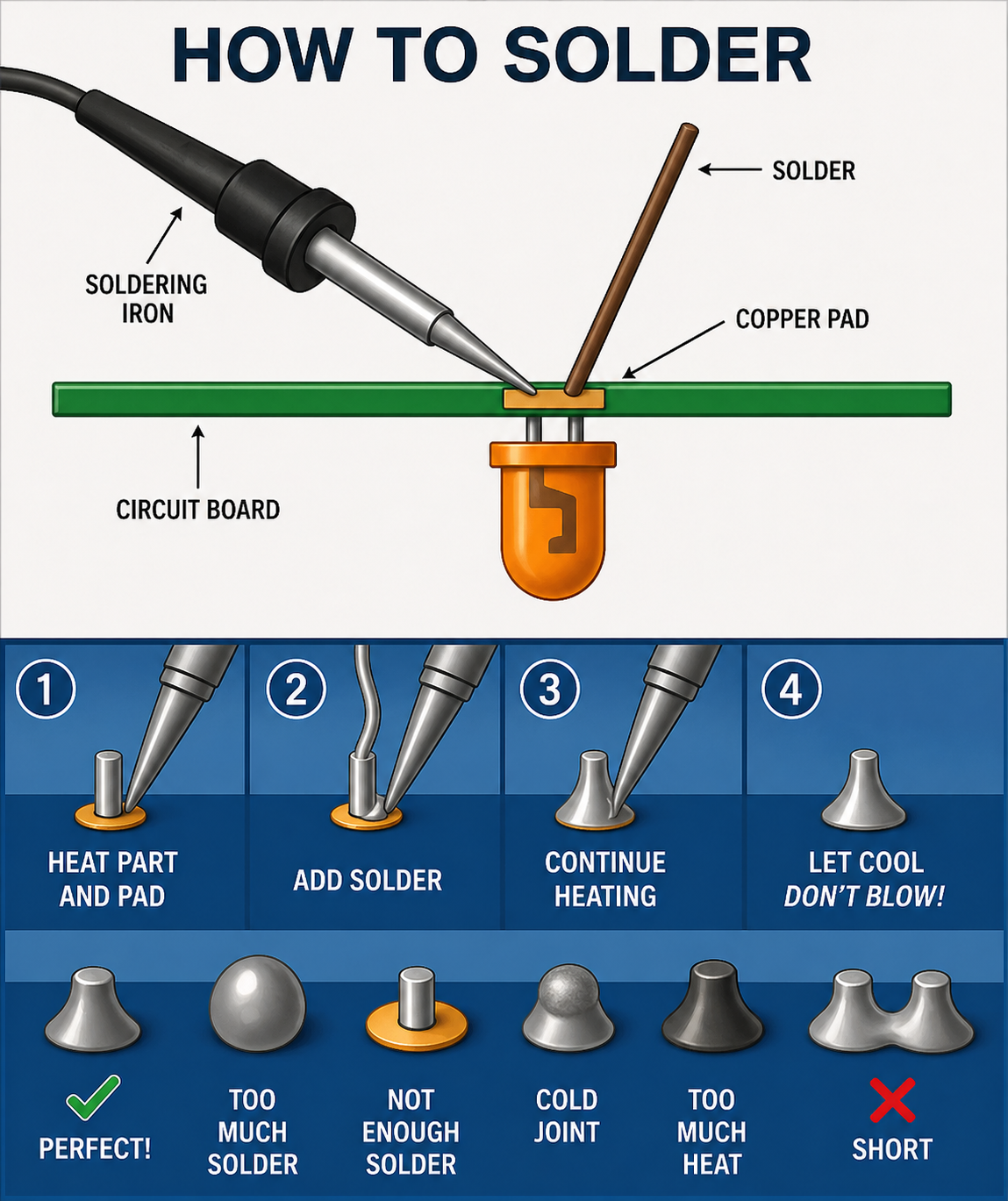
- get good at soldering. Use a small pointed tip, and get the temp right so you can get a good solder as quickly as possible. With my rig 7 seconds is about all it takes.3 second to warm up 1 second to melt the solder and 3 second to be sure it flows around the pad. Barry’s boards are pretty robust but you can still damage any board by getting the pad too hot.
Other tips
- start with the components that lay the closest to the board and work your way up. resistors first, then diodes. then usually sockets and small MLCC caps then the box caps and electrolytic’s last. I use a small piece of electrical tape sometimes to hold components in place.
- Get good at de-soldering. I don’t like using the braids. I use a pump that looks like a large pen that has a plunger and a button to trigger the suction.
- take your time soldering switches and pots, give a good 30 seconds at least, between soldering the leads to avoid overheating the guts.
I hope that helps
April 26, 2026 at 12:16 pm #38961BarryKeymasterThe Phaser is one of the few PCBs that requires standing resistors unless you’re using 1/8″ resistors (which most people don’t have on hand). It’s simply the only way everything will fit on the board. So if you’re using standard 1/4″ resistors, you’ll need to install them vertically.
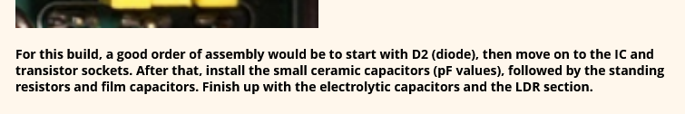
As mentioned earlier, it’s best to start with the lowest-profile components first. Just keep in mind that once installed, standing resistors will sit about as tall as the film capacitors.
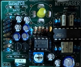
For this build, a good order of assembly would be to start with D2 (diode), then move on to the IC and transistor sockets. After that, install the small ceramic capacitors (pF values), followed by the standing resistors and film capacitors. Finish up with the electrolytic capacitors and the LDR section.
Here are a few additional reference photos:
Resistor orientation doesn’t matter, so no need to worry about which way they face (see above).
It’s also a good idea to use the BOM as a checklist while you go—it helps catch anything you might otherwise miss.
Even experienced builders make mistakes now and then, so take your time and don’t rush it. And be sure to read through the guides—they’ll save you a lot of trouble.
These ones most of all!
April 26, 2026 at 10:05 pm #38963Vokinn72ParticipantThank you guys! That has pretty much filled in the gaps that I needed!
I’ve printed out, read and re-read the guides to make sure I understand what they are telling me. The standing resistors is something I was curious about after seeing a photo of a completed build so thanks for clearing that up.
I’ve already built a $20 kit so am confident with my soldering skills (not OVER confident though). I also added a Seymour Duncan Hotrails pickup to my strat and it works! I have a Weller soldering station with a fine tip, 2 different de-soldering pumps and every thing else required to set up a soldering station including magnifying glasses, PCB holder, other tools and flux etc.
I’ve also watched a million videos on soldering, different components and how to read schematics but there were still gaps. All the info above is gold for me. Really appreciate it!
Thank you all so much. Time to stop procrastinating and start building. I’ll keep you updated on the build (probably have more questions as I go) and will post pics once completed! Looking forward to it!
Nik.
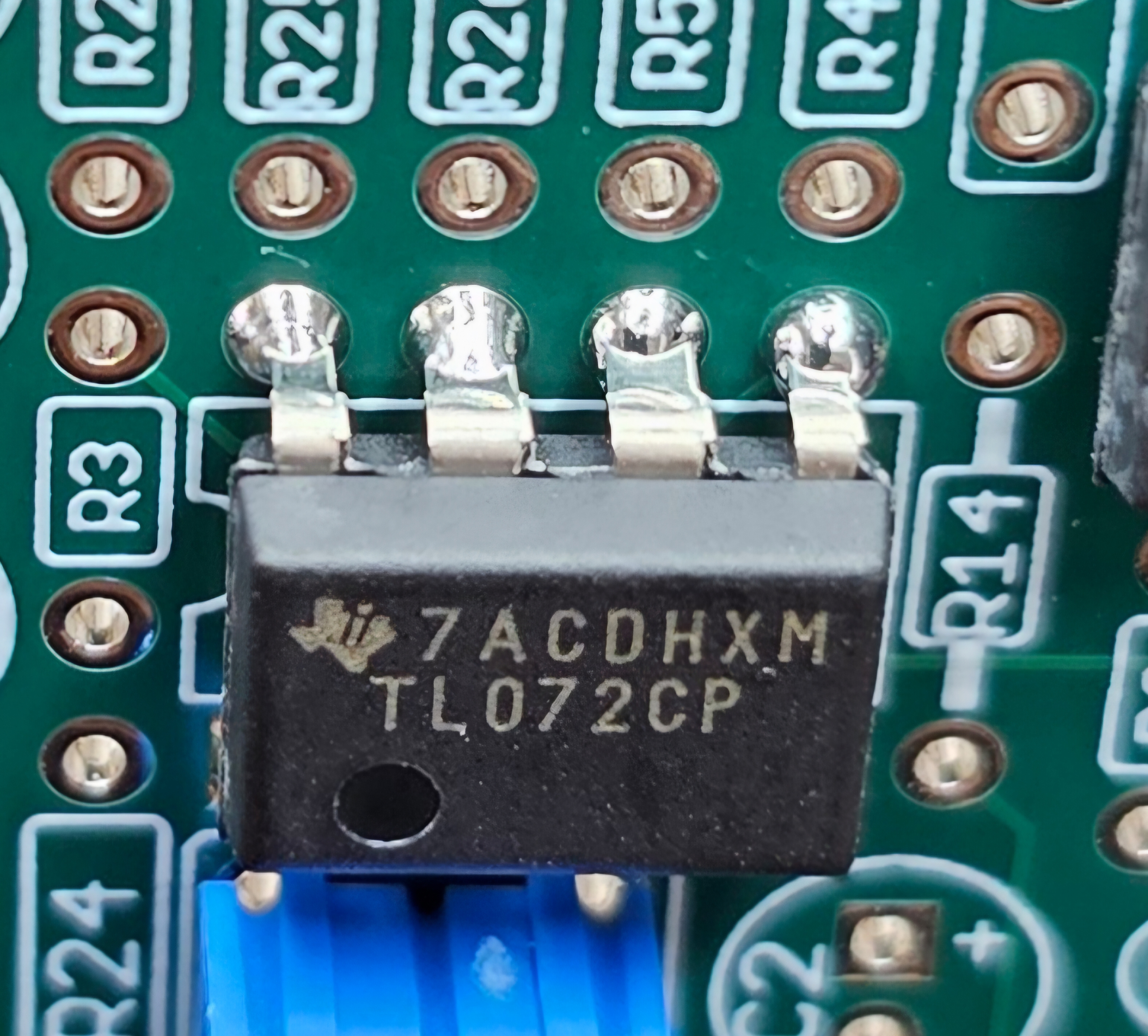
April 27, 2026 at 8:21 pm #38968Vokinn72ParticipantSoooooooo. I soldered the IC’s directly to the board … then found bases in another bag. Does it matter that they are soldered directly? Do I need to tske them off? Has the heat potentially damaged them and I need to replace them?
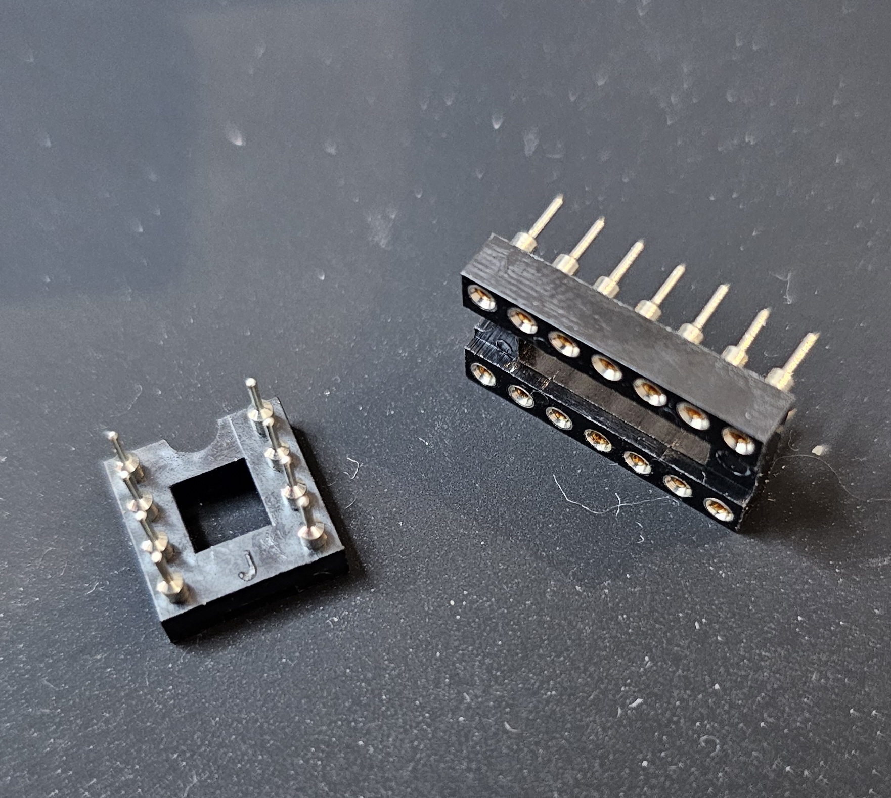
April 27, 2026 at 9:59 pm #38969brdParticipanttip #4 use sockets for all IC’s and transistors.
I don’t know of any way to test the IC’s until it’s finished.
I think I would wait and see There is a chance they have been damaged by the heat already, but de-soldering them will just increase that chance plus you risk damaging the pads on the board. The only difficult point I can see is the pads for the large IC will be under the Volume pot when it’s finished. On the other hand if you already have replacements it could be easier to do it now. Tough call.
Maybe wait for another opinion.
April 27, 2026 at 10:03 pm #38970Vokinn72ParticipantI’m chiselling these tips into my forehead lol. Don’t have replacement parts but I’m thinking I’ll go ahead with the rest of the build and see what happens. Lots of lessons being learned as I go and if it is damaged it’s really only cost me $50. I can live with that.
Just ordered another kit from pedal parts just in case.
April 28, 2026 at 3:48 pm #38974BarryKeymasterIt is perfectly fine to solder IC Chips to the PCB if you are good at doing it without over heating them. I do it all the time. I did say above in my post that the first things to solder are the Diode and Sockets.
Previous post:
Another good reason for socketing is in case you solder the chip in the wrong orientation or want to switch out a bad chip.
Anyway I would just go ahead and build it up but take your time and carefully plot your course.
April 28, 2026 at 5:39 pm #38976Vokinn72ParticipantLessons learned Barry! Won’t ever do it again that’s for sure. I’ve made some progress on the board since then. Learning to use my multimeter as I go as well. 🙂
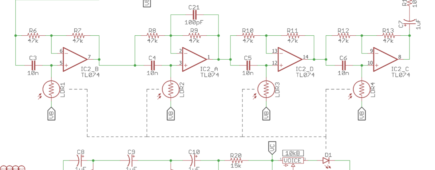
April 29, 2026 at 4:21 am #38980Vokinn72ParticipantHi Guys, couple of questions about the LDR install.
First is pure curiosity. Which part of the pedal is it interacting with? Volume? The phase effect?
Second is regarding the build. I’m assuming since they are a resistor there is no positive or negative end and they can be installed in either direction? They just need to be faced towards the LED?
Any tips for the install would be, as usual, very much appreciated!
April 29, 2026 at 1:30 pm #38981BarryKeymasterThe LDR itself is very simple and has no polarity, so orientation doesn’t matter. If it did, it would be clearly noted in the build document, the schematic, and indicated on the PCB silkscreen.
If you check the schematic in the build document, you’ll see how that each LDR ties into a phase-shifting stage, which is the core of the circuit. Each stage shifts the phase of the original signal by up to 90°.
If you want to learn more about what a Phase Shifting Stage does you can read about it here:
https://www.electrosmash.com/mxr-phase90
I would not be over-critical about the LDRs and install them as seen in the photo in the build document.
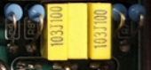
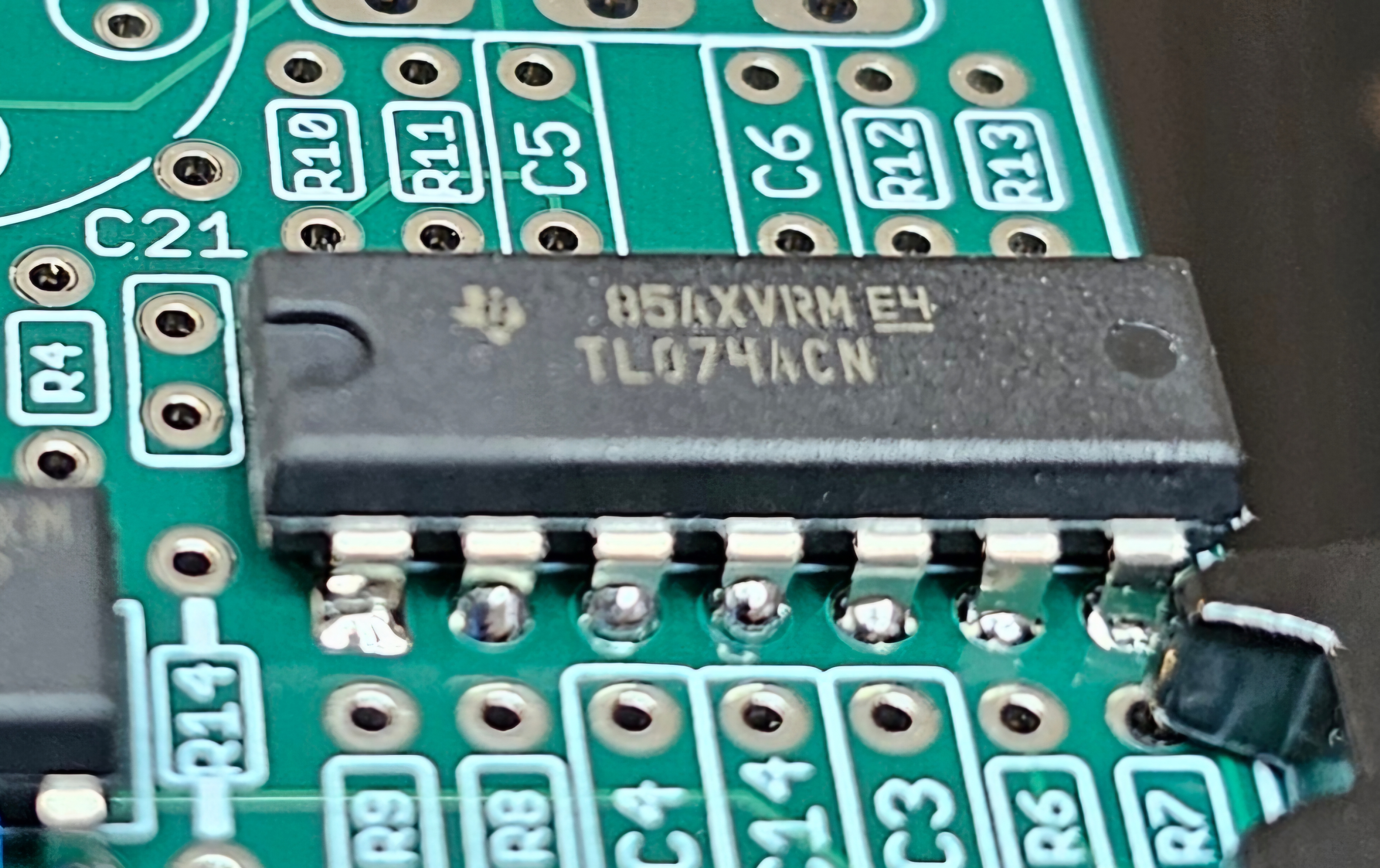
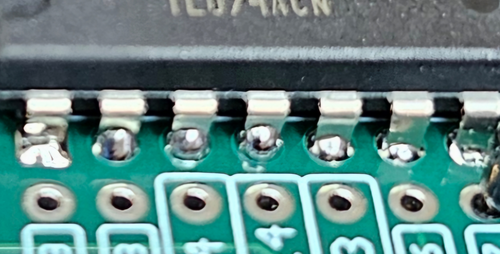
Looking at this photo, it seems like there are balls of solder on the component side of the PCB. That’s a concern, as it can lead to cold solder joints. It only takes one of those to cause the build not to work.
It should just be enough to flow into the joint and not push through to the component side.
It is OK for some to come though to the component side but I felt this is worth pointing out. I would leave it alone for now but make sure the solder side of the PCB looks like the reference solder joint above.
-
AuthorPosts
 The LED has a flat spot. The positive side is the Anode, the negative side is the Cathode.
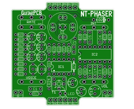
- You must be logged in to reply to this topic.