@barry
Forum Replies Created
-
AuthorPosts
-
 BarryKeymaster
You are going to have to show us how you wired it somehow.
There seems to be a wiring issue somewhere.
Many more pictures or draw it out.
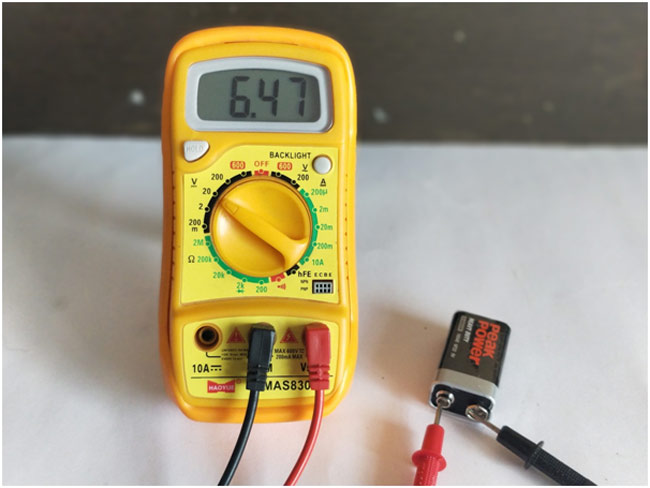
You can also confirm your connections using a DMM.
This chart is old but still useful for troubleshooting.
BarryKeymasterThank you. I appreciate that!
Cracker Jacks with a much more useful prize.
May 3, 2022 at 6:39 pm in reply to: So is there a trick to soldering board mounted pots? No melted caps… #24376BarryKeymasterPerhaps the better solution would be to use MLCC in around the pot lugs (or everywhere).
These cap types are cheaper, don’t melt when touched and have a much smaller profile which includes a 5mm spread. Even if you buy kits it is good to keep these in popular values handy anyway.
Oh an they sound just as good.
May 3, 2022 at 5:54 pm in reply to: So is there a trick to soldering board mounted pots? No melted caps… #24374BarryKeymasterSo I suggest to experiment with Tip types and of course it requires a bit of finesse and practice.
We have all burnt a cap corner but the more you do it the less it happens.
Board space is of a huge premium not just to fit into an enclosure but for my costs so I can sell at a reasonable rate to all of you.
BarryKeymaster@ Gio – You should start your own thread.
Just because it is not working does not mean it is the same problem.
Dan sorted his out by getting a proper set of matched transistors.
We need more information like where did you get your transistors, which ones are you using and what are the voltages.
BarryKeymasterI think Wilkie has you covered.
His response looks like it crossed in the mail after the fact.
BarryKeymasterI would absolutely be using the Sag pot.
In retrospect I am not sure why removing it was ever mentioned as an option.
You can put a 1N4001 in the D2 slot.
BarryKeymasterYes I agree with Bruce in that I saw this original Muff Rams Head dissected that had 10uf caps at C1, C2, C13, a .05uf cap at C7 and a .0068uf tone cap at C8. So EHX shoved whatever they had in stock on any particular day (which Bruce already mentioned) for the coupling capacitors since lower frequency did not mean anything as it was all below what was required for guitar or Bass.
That said IMHO the actual important things to consider are:
- 10uF electrolytic can possibly go bad. (as in the thread above)
- 10uF caps are hard to find in other capacitor materials.
- Don’t use a Tantalum unless you are 100% sure of the orientation
- capacitor values from 1uF to 10uF will make (0) sonic difference with guitar or Bass
If you are after copying an original only then there really is no true original based on the dissected build in the thread above as well as the iterations covered by kitrae.
At the end of the day I would go with the EHX’s schematic and use a 1uf film cap. That type will last forever and has bottom end down to 3hz and if that is too boomy then substitute that for a 100n like most of the other variants.
BarryKeymasterI would be remiss if I did not point out the “Official Schematic” hand drawn from the same link as above shows a value of 1uF for C1 dated Oct 15/1975 which is Rams Head because of THIS. BYOC and General Guitar Gadgets interestingly all have the same typo as well.
Also no mention of changing the value to 10uF anywhere. I would find that odd if it were not a typo.
Wilkie1 pointed out that 1uF gives you Bass frequency to 3hz.
Guitars do not reproduce 3hz (movie theater rumble) let alone what 10uF would drop that to so it is kind of a ridiculous value. I will make a note of that in the document.
BarryKeymasterI would not use a Tantalum. Get it wrong and there could be fireworks.
Use a 1uF at C1. I believe 1uF is a typo I have to fix.
BarryKeymasterHi, the reason for 4 holes is to allow for two different both common types of Trimmer pots. Either will fit.
Again we are all about options, especially money saving ones.
Yours will fit as is.
You must install the correct trimmer in T1 as it is a Bias trimmer.
Per Document: T1 adjusts the Bias of the boost portion of the circuit. To set bias, measure the voltage (using your DMM)
between the drain of Q1 and any ground. Adjust Trimpot (T1) so that the voltage on the Drain Leg of J113
is 5V or perhaps higher (up to 6V) if you require higher output level.Finally do not install T2 as it is one or the other. You have opted for an enclosure mounted Pot for Boost/Volume.
I hope that helps.
BarryKeymasterAre you using protection on the back of your pots so as not to short out against the board solder joints?
Also is that a Tantalum cap at C10, the yellow one or is it MLCC?
BarryKeymasterIdeally it is best to test each circuit on their own to rule out other issues.
So if you did not do this first I suggest carefully holding an iron to the pads (one at a time) on the Easy Order switching board and removing the wires so you can test the Muff’n by itself.
This will leave a bit of solder in the pad but that is fine. Simply reheat the pad and push the wire back in after solving the issue. (with some careful finger dexterity and wizardry).
If the problems are identical double check off-board wiring and fix or re-flow where needed.
If you are still having issue then test each transistor by itself with your DMM
Put the DMM on V or volts (DC).
Put the black probe on any ground of the board or wiring. Put the red probe on each pin of the transistor and record the reading.
List them here in a format that is easy to read like:
Q1:
E:
B:
C:
BarryKeymasterYou may leave a CLR in place where it is not being used. It just won’t be going to anything and it is outside the audio path so it has no affect on the effect whatsoever.
You may use anything from 1.8k (brightest) to 4.7k (dim) with success.
BarryKeymasterEither way is fine use your preference.
If you want the LED mounted near the foot switch use the wiring board. You will also need to add a CLR there since it is not connected to the main board. If you want the LED mounted where it is on the main board is then use it there. Again you will need the CLR on the main board.
If it is a kit and pre-drilled above the foot switch then you will need to use the wiring board and add a CLR to it.
People have all different kinds of preferences so we provide options to meet most people needs.
BarryKeymasterLooking at this picture:
I suggest pushing the wire in till the pvc jacket hits the board.
You can fix all of these wires by doing a re-flow. Heat pad till wire pushes forward using the technique described below.
Solder while holding the wire in place (requires some dexterous finger work) making sure the pad fills with solder. My technique is usually to hold the board on edge against my work surface with my pointer finger at an angle while using thumb and middle finger to hold the wire in place while I solder.
Using flux can help if needed depending on what solder you have.
Be sure to use a fine conical tip.
Using sockets would be an accident waiting to happen.
You just need to keep practicing your solder technique with wires to the board.
BarryKeymasterWe need the voltages for all J201 posted.
-
AuthorPosts