@billy
Forum Replies Created
-
AuthorPosts
-
 BillyModerator
Your voltages look too low If it’s a battery only you’re using try a fresh one
Pin 8’s your supply voltage should be around 9v with pin 5 your V out – 9v
The readings you’re getting 6.59v going in are more or less a flat battery
Oscillation can be caused by many things one of which is incorrect voltages so hopefully it’s just a dud battery so try a fresh one first
I’ll move your post over to the build support forum
BillyModerator+1 looking at the schematic you’d need a jumper between the ‘T’ tip pads
BillyModeratorI’d suspect a ground problem with those high readings on your IC or the op amp itself
Zooming in on your ground connection I’d reflow that so it melts nicely onto the pcb pad and DC jack it may well be a poor connection coming loose so check all of your grounds and IC socket pads especially pin 4 ground even though it’s reading 0v your input and output pins 2,3,6 should read around half the supply voltage with ground on 4 and supply voltage to 7, check that the IC is located correctly into its socket
Also take voltage readings with the IC removed from the socket for comparison
You can also wiggle each wire to see if it can be replicated to find any bad connections
As Wilkie says if a socketed component comes loose that would cause problems on a recent Mowah build I had a socketed transistor causing an intermittent fault when the wrong way up it was fine turning it around it crackled then cut out I eventually found one of the legs had broken with me constantly checking voltages
So when I turned it around the broken pin would connect and visa versa dis connect took me a while to suss it it was only when I removed it I saw the pin had broken inside the socket
BillyModeratorIf it’s a pop when you switch it on and off firstly check R2 has good connection by reflowing the solder joints then try soldering a wire from 3PDT lug 1 (input) to lug 6 as below to ground the input when switched
BillyModeratorOofft that’s an absolute beauty
Looks great inside and out, you’re a natural
Really good build well done to you and a great example of what can be achieved with a little help from the guides a lot of folks don’t read them or watch the videos and quite often end up with errors mostly outlined in them
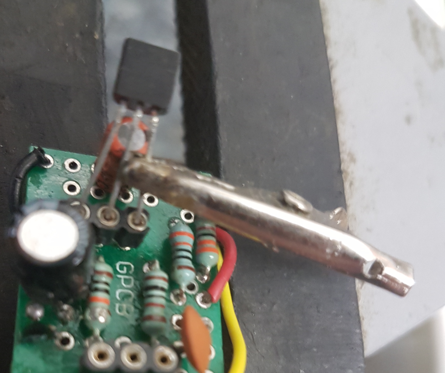
A little tip if you’re keeping the diodes and transistors you’ve selected use a small crocodile/ alligator clip as a heatsink and solder one leg into the sockets so there’s no chance of anything coming loose and falling out
BillyModeratorIt’s a film cap highlighted because it may not be obvious from the BOM
I use MLCC here some of the 1uF film caps can be pretty big but as you can see from the silkscreen you can fit them in
BillyModeratorFrom your voltages all being high it looks like a grounding issue
BillyModeratorThat narrows it down a bit Shane are you getting 9v on the pcb when connected up to your test box
Hopefully from what you’ve said you don’t have any faults in the circuit and it’s either not getting power or your in or out wires have bad connections on the pcb T pads
Funnily enough your colours of choice are the exact opposite of mine I use green for in and yellow for out
BillyModeratorJust to verify my photon phuzz does have continuity between D2 cathode and +9v and D2 anode and ground
Zooming in on your pcb it does look like you have heat damage to some of your solder pads particularly the in , out, 9v and ground pads I also note you have your transistor soldered directly to the pcb hopefully it’s not been damaged
These are double sided pcbs so you can solder to either side of the pcb if any of the solder pads have been pulled off with too much heat from your soldering iron
Post a picture of your 3PDT switch wiring so we can trace your wires from the pcb to 3PDT and from the jacks to 3PDT
BillyModeratorA 50K log will do the job Bill
Pots have a 20% tolerance so a 47K could be anything from 37 to 56K
BillyModeratorNice build! graphics are great Gabor really pro looking
BillyModeratorNo bypass is most probably a dry solder joint on the switch and hopefully not heat damage to the lugs from soldering
Click the switch to bypass mode and check you have continuity along the red lines
BillyModerator+1 as Barry says voltages, tolerance etc for parts are in the Beginners Guide to effects pedal components
If you still have your previous build post a troubleshoot with clear pictures you may be able to rescue it
It’s always better to post if your build doesn’t fire up that way you’ll learn why and hopefully avoid the same problem with future builds
I too have built many pedals with my last one I wired the DC jack in reverse a basic error fortunately I didn’t fry it when I plugged it in its a constant learning process for all of us so always better to find out why it didn’t work, solve it and learn
BillyModeratorDA and DB are single colour standard LEDs in case you prefer it to or don’t have a common anode bicolour LED
BillyModeratorHaha not just you James mate I’ve made many…..way too many
It was just a wee chance to mention it once you posted your picture it was obvious but usually never obvious at the time to the builder so you assisted with that clear image
That plus I’d noticed recently a lot of errors are answered in some of the guides and I know having given links to beginners on other forums they’re usually not read the giveaway being when the recipient asks me a question answered in the very PDF link I gave them
With the work we all put in I sometimes think if people read it thier building would be a lot easier, so it was just a gentle reminder to read it and not weep!
I recently built an expensive combo and managed to wire the DC jack in reverse + plug it in fortunately for me I never toasted it and that’s after God knows how many builds and I should say I’m glad to see you back always nice when people are in good health and back on the forum so I’m happy to hear it
BillyModeratorGood opportunity to say to everyone that’s why pictures etc are so important with troubleshooting posts we’d have all been swift on the keyboard trying to solve an easy one with an image
Us mods do like being quick solvers haha and as our friend Pete was mentioned I used to enjoy seeing who had the quickest trigger finger alas Pete used to leave me in his wake but it was great fun us both keeping score fond memories indeed
He most certainly was eagle eyed Cap’n legend in my eyes
BillyModeratorWhen exactly does it crackle just when you switch it on and off or in general when you’re playing through it turning pots etc
There are many things that can make it crackle from cables to jacks power supplies etc bad connections on pots dry solder joints faulty components and so on
You can do the wiggle test to try to locate exactly where it’s coming from use a pencil or something non conductive and gently tap on the components and wires to locate the source and hopefully rectify it
You can test your LED in place using a 3v coin cell battery just slide it in between the legs + to the middle pin and – to the outer pins to see if it illuminates if it was working prior to putting it in your enclosure make sure the pins aren’t touching any bare metal parts
-
AuthorPosts