@billy
Forum Replies Created
-
AuthorPosts
-
 BillyModerator
It says in the build document
R25-As noted at the bottom of the parts list, the 2N5133 was lower gain, in fact, the specs state the minimum gain as 60hFE, whereas the 2N5088 has a minimum gain of 300hFE. If you use a 2N5133, R25 should be a jumper. If you use a 2N5088 or other higher gain transistor, you will need to insert a resistor in R25 to keep the pedal from squealing when all knobs are turned completely up. 33K is a good value to start with. A stock Mayo calls for the2N5133 and a 2k7 value in R25, but this same guidance applies if you change transistors
A BC549C is a higher gain transistor, the gain in this case refers to the hFE or β (beta) value of the transistor
http://www.learningaboutelectronics.com/Articles/What-is-hfe-of-a-transistor
BillyModeratorIn the build notes it advises if you use a high gain transistor like the BC549C you should use a resistance of 33K as a starting point so I’d socket R25 and try different values
The BC549C can go from 100 to 800 hFE according to the datasheet
The ones I have all test using a DCA55 from 420 to 560 hFE
BillyModeratorThe decay pot lug 1 does connect directly to ground
The depth and attack pots don’t, attack is connected to ground via R19 If you look at the schematic you’ll see how they’re wired and where you should expect continuity
If I understand correctly you are saying that all pots don’t have much range across thier rotation and they go from min to max very quickly?
Double check you have the correct value pots in the correct positions there’s not a huge difference in pot values but if you put a B2K were a B10K should go then the range would be affected
As Barry says check all component values and orientation it’s very easy to use an incorrect value in a fairly high parts count build
This is what I use to check resistor values
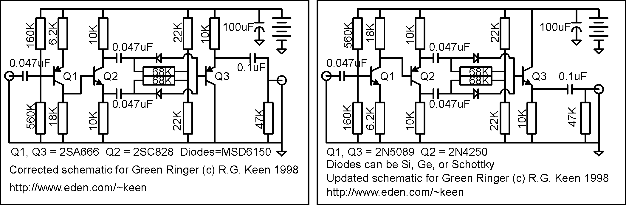
BillyModeratorThe MSD6150 dual diode is mentioned in these RG Keen schematics it’s common anode the one on the left shows it, note the anodes are connected to Q3 whilst on the right the cathodes hence the update I’m assuming
BillyModeratorBoth could work
The 50K wired as a variable resistor would be what I’d try initially you could socket R15 and try the pot to see what you prefer measuring the resistance at each one
You could also still make it foot switchable using a dpdt board one side with the standard 47K and pot the other side, you could also do the same with the roto tone or use a 3PDT to indicate it’s on with an LED
Check the roto tone build doc for ideas on how you can implement it
BillyModeratorNice Mr Wilkinson sir!
BillyModeratorR23 looks like a 3K9 instead of a 3M9
BillyModeratorThe transistor pinout was just a heads up as Barry says an audio probe is definitely a good option
Wilkies got it covered! to make it a little easier for diagnosis you should label the transistor pins as
C B E (Q5) and D G S (Q1 – 4) instead of 1,2,3
BillyModeratorCheck the BC557 has the same pinout as the 2N4125
BillyModeratorNo you’re thinking correctly im not! you should depending on the CLR value get less than 2v on the actual LED pads
If you didn’t blow your first LED with 9v then the LED wasn’t conducting continuity check all your connections 9v pad to CLR right side CLR left to anode and cathode to ground also check your 3PDT has continuity in effects mode and is grounded
Post a picture of it so we can have a look
BillyModeratorHave you got the anode + going to the centre pad and cathode – to the left hand pad the one without the white box
It can’t be much that’s wrong, sounds like you could have the LED anode and cathode in the wrong pads
You’d get 9v on the LED because there would effectively be no path to ground
BillyModeratorAre you checking voltage on the left side of the CLR resistor? is your LED a common anode bi colour or a single colour LED
BillyModeratorhttps://guitarpcb.webs.com/PDF%20Files/MastadonFuzz_v2A.pdf
This is the build doc for the onboard 3PDT MaFu
BillyModeratorNot sure what C1 and 3 are, are you talking about the collectors on Q1 and 3
You bias Q3 collector to around -7v using the trimmer or by ear to where you think it sounds good I almost always do it by ear there’s no hard and fast rules if you think it sounds good, voltages are irrelevant from that point of view
As you can see in the build doc people get different results with different bias voltages
BillyModeratorWith regard to your common anode bi colour LED you should have continuity as follows
Note all 3 square +9v pads have continuity with the CLR so it doesnt matter which one you use
BillyModeratorReflow all your joints Dustin a dry joint could also cause oscillation also check it isn’t coming from your MAX1044 touch the IC solder joints to see if it affects it
I just realised I’ve been looking at the PUFF schematic instead of the PUTB doh! I’m actually working on a PUFF at the moment
BillyModeratorDo you have the IN ‘T’ pad from the pcb going to your switch
Just in case you don’t know your in and out pads have a small T for tip pad with the other pad being ground can’t see where they go to or whether your clip is also touching ground on the pins you’ve soldered on the IN and OUT pads
If you’re using an audio probe check from the IN T pad to see if audio gets in there it could be that your connection is grounding the signal just make sure you attach the clip to the T pad without it touching the ground pad next to it
If you’re putting a signal in at Q1 C it tells us everything after it is OK prior to it you have the IN T pad to R1 to C1 to the base of Q1
How are you inputting signal at Q1 C
-
AuthorPosts