@billy
Forum Replies Created
-
AuthorPosts
-
July 18, 2026 at 10:01 pm #39473
 BillyModerator
Sorry been working so not had a look for a while
I’ve had a quick glance at your pcb particularly orientation of polarized components which all look correct
Just to clear up some basics do you get no sound at all or no effect but bypass sound
Without powering the board use your meter diode test to check D5 you should obviously only get a forward voltage reading in one direction and OL or 1 in the other then power the board and check if you still get voltage on D5 cathode check voltages on IC6 pins and pin 1 of the BTDR3
You’re basically trying to work out how far power gets to in the circuit and hopefully narrow down your problem area
You don’t really want to change or replace anything without reason or it will get confusing
July 16, 2026 at 12:49 am #39449BillyModeratorPost an image of the populated pcb it’s very easy to miss something even after multiple checks
The scratch as said doesn’t look too deep and that part of the circuit just looks like a low pass shelving filter to dump higher frequencies to ground
Lug 2 as you can see connects to ground and looking at the pcb image there’s no traces above the pot the 9v rail runs below it
June 25, 2026 at 1:56 pm #39378BillyModeratorJust for info most trimpots used in guitar effects are linear B taper you can get log A taper but they’re more for specialist use
May 27, 2026 at 1:59 pm #39179BillyModeratorIf you’re going to try a parallel capacitor I’d say 100n for hf noise there’s already the 100u in parallel with the voltage divider
I’d use the unscientific method of dabbing your finger on and off the op amps to see if you can narrow it down without hearing it we don’t know if it’s oscillation
Do you have the R12 jumper on a switch if so does it make the noise in the normal position
Post an image somebody might see something I know I’ve missed incorrect values etc after multiple checks it’s easily done
What pickups are in your guitar is your power supply filtered and regulated
May 22, 2026 at 12:06 pm #39158BillyModeratorWhat transistors did you use for your forum vibe some layouts show the original Japanese transistor pinout where the collector is the centre pin it looks like the forum vibe pinout is EBC with the dot at E on the pcb image so if you’ve used Japanese 2SC types then it could be that
If I’ve had trouble with univibe builds it’s usually that where I’ve swapped transistor types to more modern easier to find replacements then forgotten about the different pinout
For the vibe I’d try a 100K trimmer in place of R14 and lower the resistance across it to see if that increases the vibrato effect
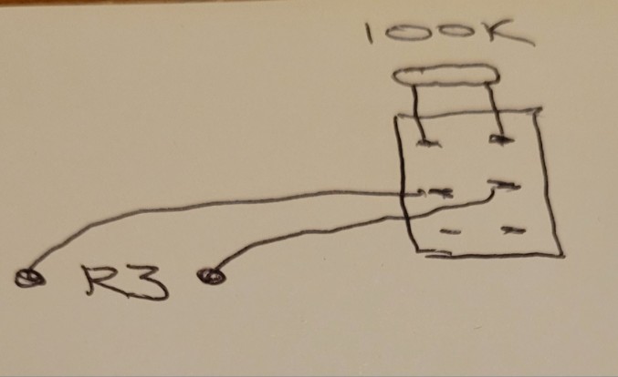
May 22, 2026 at 10:22 am #39156BillyModeratorI think it should work if you look at the forum vibe schematic here although it uses transistors and a lamp rather than op amps and an LED it’s basically the same with the chorus vibrato switch at the output the vibe should have the wet and dry signal balanced with the two 100K mix resistors R3 and 14 so you shouldn’t need the balance trimmer, voltage divider set up you see on the forum vibe
If vibrato mode is louder or quieter you could use a trimmer wired as a variable resistor in place of R14 to set it to the same level as chorus mode if it’s quieter use a 100K louder use a 250K so you can add or subtract resistance
I’m also not sure if you’ll get any switch pop with the 1u caps
https://musikding.de/docs/web/univibe-ForumVibe-final.pdf
May 21, 2026 at 6:38 pm #39152BillyModeratorI don’t think it would be straightforward if you’re looking for the same as the original univibe circuit you’d need to add a few components
A vibrato switch would just cut the dry signal out I’d try a DPDT switch in place of R3 that’s the mix resistor for the dry signal I say DPDT but you could use a miniature DPST if you can find one like this
On-Off Mini Toggle Switch DPST — Switch Electronics | Your One Stop Component Shop https://share.google/4cprW0cAW3E3CAeov
April 22, 2026 at 10:52 pm #38942BillyModeratorIt specifies on/on DPDT switches and looks like the switch puts a capacitor in parallel with C1 and C2
So switching C1 to10n will allow more highs then adding the 100n in parallel on the switch will give you 110n close to the stock value
Same with C2 adding from 1 to 10n in parallel will roll off more highs
March 23, 2026 at 9:21 am #38805BillyModeratorNow that looks excellent
I like the idea of faceplates they look really good and anything that stops me having to sand an enclosure apply decals etc definitely appeals to me
January 20, 2026 at 11:04 am #38233BillyModeratorCheck you’ve got a good connection to G2 I’d personally have wired it direct to the DC jack
Remove IC3 from its socket and let us know the voltages on the socket
January 14, 2026 at 10:04 pm #38221BillyModeratorYou’re correct volume 1 goes to ground so a jumper will work
I’ve only got the V1 build document which doesn’t have R11 but I’d guess R11 would be 1K max if for some reason you don’t want your volume to go all the way off
January 4, 2026 at 3:00 pm #38163BillyModeratorJanuary 2, 2026 at 4:29 am #38153BillyModeratorIt should work OK with any pnp transistor and your matched set of jfets if the LFO isn’t oscillating that’s your problem I’d check all components in that section
I’ve had solder joints that looked perfect but where dry inside not often but you never know
January 1, 2026 at 6:50 pm #38151BillyModeratorThose look like pnp transistors not jfets
December 31, 2025 at 3:35 am #38145BillyModeratorDoes pin 6 voltage still oscillate regardless of the speed pot
It should if pin 2 oscillates
Try reflowing C8 solder joints
I’ve got a phase 90 circuit somewhere I’ll try to find it and confirm voltages etc unfortunately I had to empty my workshop to get some work done to my house recently so hopefully I’ll find it easily enough
December 29, 2025 at 8:42 pm #38132BillyModeratorIC 1 and 2 voltages look good
What PNP transistor are you using for Q5
I wouldn’t swap out any components unless you know they’re a problem you risk lifting solder pads etc with too much heat
The IC3 voltages we’re most interested in are the input pins 2, 3 and output pin 6
Although I said the trimmer doesn’t directly affect the LFO voltages it does affect the JFETs I don’t want to get into too much technical detail that I’m not 100% on myself but afaik basically the LFO oscillating output controls the resistance between the FETs source and drain pin via the gate the JFETs are being used as voltage controlled variable resistors
So what we’re trying to establish is that the LFO works and the FET gates are set to the correct voltage
As you’ll know FET parameters vary wildly even from the same batch hence why you need a matched set so they work together
What is the voltage on the other side of R23
We need to know for sure if the LFO is working pin 2 and 6 oscillating will confirm that
The speed pot works in conjunction with C8 to set the rate so as you turn the speed pot from slow to fast C8 charges and discharges at a different rate which you should see on those pins set the speed pot clockwise a little under a quarter turn then slowly turn it up and you should see a difference in the voltage oscillating rate
Troubleshooting is sometimes a long process but as I say you’re better checking everything before changing random components in the hope that it works as I’ve said it could well be a poor solder joint it’s just a process of elimination that eventually leads you to your fault
December 28, 2025 at 11:51 pm #38129BillyModeratorAre you reading your IC pin numbers in the correct order
Pins on the left hand side are numbered top to bottom and the right hand side bottom to top
-
AuthorPosts