
Your Source for DIY Pedal PCBs and NostalgiTone! › GuitarPCB Forum › GuitarPCB Build Support › Black Dog (answered)
- This topic has 9 replies, 4 voices, and was last updated 7 years, 6 months ago by
 Anonymous.

-
AuthorPosts
-
March 27, 2019 at 9:42 am #5010AnonymousInactive
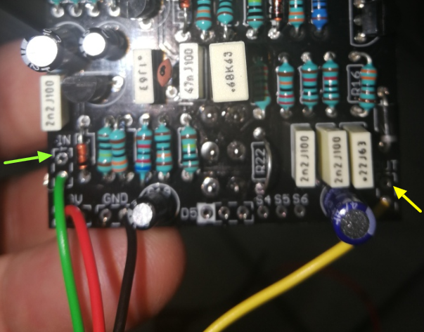
Hi everybody I finished to build the black dog project but when attached to guitar and amp there is no signal seems that the signal does not coming in or out, the current seems to be ok led is light
i post some picture if someone can help me
thanks
March 27, 2019 at 10:55 am #5011BarryKeymasterConnect the Green and Yellow In/Out wiring on the Main Board to the (T) Pads.
Currently they are connected to ground.
This image is from the Guides Page. It would be great for printing out as all builds follow this example:
If you need further help I would start by first verifying everything against the Image above.
March 28, 2019 at 5:46 am #5024AnonymousInactiveThanks Barry I tried to follow the picture but still issue, there is a lot of buzz ground rumors and when I touch the buzz increase
March 28, 2019 at 9:47 am #5025CybercowParticipantI fail to grasp why R22 has a jumper in that location. I can see that you are NOT using the on-board LED indicator, but that’s no reason to jumper the on-board CLR (R22). I’m also aware that it likely has no bearing on the noise issue.
Also, I can see there is no ground wire on the input jack. Without a ground wire going to that input outside of the box, the ground of the circuit is not complete. Try adding that ground wire to the input jack.
March 28, 2019 at 9:59 am #5026AnonymousInactivethanks , I cut the jumper and put the ground on jack but still not working lot of ground noise especially if I touch the PCB
March 28, 2019 at 10:33 am #5027BarryKeymasterYou still need to fix your Main Board Out wire (yellow) by using the T pad. I put arrows pointing to the T Pads in my 1st photo post above.
The T Pad is located by the visual T on the board silkscreen. Depending on the Main Board it is not always simply on the top or bottom so you have to visually verify. T stands for Tip which is the Audio Path.
It will not work if you do not connect the Audio Path properly.
I also noticed resistors not seated properly and a lot of dull grey solder joints.
If it does not work after fixing the Yellow OUT wire I suggest watching my Soldering Tutorial.
You may have to carefully redo some solder joints. Be careful not to heat the transistors since you did not use sockets to protect them from the heat of the soldering iron.
Also helpful you can refer to our GUIDES PAGE which may help you more.
Anything Orange is a LINK. Click above.
I hope that helps.
April 17, 2019 at 5:39 am #5257AnonymousInactiveHi Barry, I re-built the black dog now is working but in by pass mode there is no audio signal, it works only when the pedal is engaged, what could be the problem?
thanks
Angelo
April 17, 2019 at 12:50 pm #5265BillyModeratorNo bypass is most probably a dry solder joint on the switch and hopefully not heat damage to the lugs from soldering
Click the switch to bypass mode and check you have continuity along the red lines
April 17, 2019 at 7:26 pm #5268AnonymousInactiveI checked continuity there is pin after pin not if checked from the begining to the end of red line you mentioned
April 18, 2019 at 3:11 am #5380AnonymousInactiveSolved it was the jumper that was unsoldered Thanks
-
AuthorPosts







- You must be logged in to reply to this topic.