@billy
Forum Replies Created
-
AuthorPosts
-
 BillyModerator
Does pin 6 voltage still oscillate regardless of the speed pot
It should if pin 2 oscillates
Try reflowing C8 solder joints
I’ve got a phase 90 circuit somewhere I’ll try to find it and confirm voltages etc unfortunately I had to empty my workshop to get some work done to my house recently so hopefully I’ll find it easily enough
BillyModeratorIC 1 and 2 voltages look good
What PNP transistor are you using for Q5
I wouldn’t swap out any components unless you know they’re a problem you risk lifting solder pads etc with too much heat
The IC3 voltages we’re most interested in are the input pins 2, 3 and output pin 6
Although I said the trimmer doesn’t directly affect the LFO voltages it does affect the JFETs I don’t want to get into too much technical detail that I’m not 100% on myself but afaik basically the LFO oscillating output controls the resistance between the FETs source and drain pin via the gate the JFETs are being used as voltage controlled variable resistors
So what we’re trying to establish is that the LFO works and the FET gates are set to the correct voltage
As you’ll know FET parameters vary wildly even from the same batch hence why you need a matched set so they work together
What is the voltage on the other side of R23
We need to know for sure if the LFO is working pin 2 and 6 oscillating will confirm that
The speed pot works in conjunction with C8 to set the rate so as you turn the speed pot from slow to fast C8 charges and discharges at a different rate which you should see on those pins set the speed pot clockwise a little under a quarter turn then slowly turn it up and you should see a difference in the voltage oscillating rate
Troubleshooting is sometimes a long process but as I say you’re better checking everything before changing random components in the hope that it works as I’ve said it could well be a poor solder joint it’s just a process of elimination that eventually leads you to your fault
BillyModeratorAre you reading your IC pin numbers in the correct order
Pins on the left hand side are numbered top to bottom and the right hand side bottom to top
BillyModeratorWith the LFO not oscillating it’s obviously not going to work
The trimmer doesn’t directly affect the LFO voltage you can check pin 6 with your meter the voltage should oscillate
It could well be something simple like a poor connection or solder joint
The speed pot just controls the oscillation / modulation rate have it set at a slower speed when taking readings on lug 2
Post voltages for all your IC pins and the Q5 CBE also the voltage at the top side of the 3M9 R23 with no power to the circuit check resistance across R23 check that R24 is a 4K7 yellow purple black brown brown we can’t see it because of your wires
Make sure all your ICs are firmly locked into their sockets carefully them in until they click
BillyModeratorNo it won’t hurt setting the voltage higher or lower the crucial thing to remember is the trimmer phasing range is very small so move it in tiny increments
With 5952s you should get phasing with the gates set from anything between around 1.7v to 2.3v, in my experience using 5952s the sweet spot is usually 2 to just over 2v but try from 1.5v and move as I say slowly play audio through the circuit as you do it and you should hear it kick in then adjust for the most pronounced phasing sound
Check you get an oscillating voltage on the LFO IC3 output pin 6 you can also check on lug 2 of the speed pot
I’ve misread your initial post I actually thought you were getting an oscillating voltage from the LFO
BillyModeratorNo use a small screwdriver to turn the trimmer TR1 until you get a reading of around 2 volts on Q1, 2, 3 and 4 gate pins
The gate pin is the bottom one as circled in red below first check what voltage you get on Q1 gate pin if it’s not around 2v set TR1 to the centre position and turn it clockwise in very small increments till you read between 2 and 2.3v on Q1 gate
As I say you only need to do Q1 all the 2N5952s gate pins are connected as you can see in the schematic
BillyModeratorWhat jfets did you use if they’re 2N5952s
Did you use the trimmer to set the jfet gate voltages to just over 2v
They’re all connected so you only need to set one
If they’re not 2N5952s check the pinout is correct
BillyModeratorSounds good to me
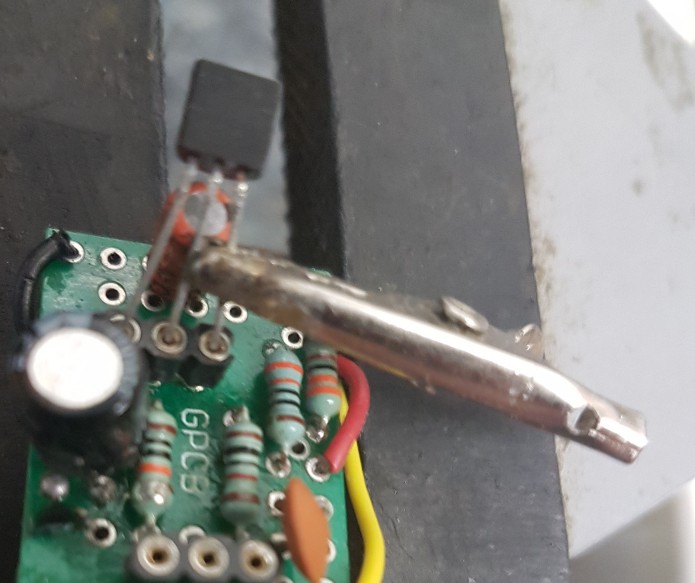
If my transistors feel loose in their sockets I use a small croc clip as a heatsink and solder one pin into the socket
If your transistors are in sockets it’s a good idea to do this then there’s no chance of them falling out when the pedals upside down or accidentally knocked or whatever
Like this clip the croc clip on a pin and put a blob of solder on your iron and carefully solder it in trying not to touch the plastic part of the socket
BillyModeratorCheck the voltages you get with Q3 and 5 removed from their sockets to see if there’s any difference
I’ve just noticed Q4 gate looks low that should be similar to Q2 with your voltage divider R16 and 17 around half supply voltage less the 0.4v drop through D1
Check the voltage you get at the two voltage divider junctions R8 and 9 and R16 and 17
Try reflowing R18 solder joints the source of Q4 should be almost the same as Q5 drain you’ll notice Q2 source is almost the same as Q3 drain in what looks like a mu amp set up so even though we don’t know exact voltages we can see from the schematic they should be very similar
If R18 is difficult to get to with no power to the circuit check resistance between Q4 source and Q5 drain which should be around 1K or similar to the resistance between Q2 source and Q3 drain
Do you know if your meter has a 1M or 10M input impedance just so we know how accurate your readings are
Anybody that’s got the pedal if you could post transistor voltages that’d be great
BillyModeratorQ1 looks OK that’s the treble boost / naga viper ish part
Q3 and 5 look off to me but unfortunately I don’t have the circuit on hand to check voltages
That’s assuming your readings are EBC Q1 and DSG pin order for Q2 to 6
I’ve probably confused that a bit Q1 pins top to bottom are EBC, Q2 to 6 top to bottom are GSD
Check C8 and 12 negative sides have continuity to ground
Are the fets 2N5485s
BillyModeratorAll your components I can see look to be the correct value and orientation
What voltages do you get on all transistor pins Q1 EBC and Q2 to 6 DSG take voltages with the range pot fully clockwise
I’d suspect a mis biased transistor from your fault description
Fets as you’ll know are all over the place even from the same batch the fact it changes when you swap them around could indicate a biasing problem it could be anything from a poor solder joint on a biasing resistor to a transistor not fully secured in its socket
BillyModeratorPost some nice clear in focus images of the component side of the pcb so that all component values and orientation can be clearly seen and offboard wiring traced
It does sound like a mis biased transistor what transistor are you using in the Q1 position
BillyModeratorGood to hear you got it going
Apologies are definitely not needed we all learn as we go none of us were born making pedals
Enjoy your new creation
BillyModeratorFlat side facing you left to right it’s CBE so place them opposite to the silkscreen
Manufacturer doesn’t make a difference for the BC549C
Meant to say I checked all your component values and orientation what I could see looks correct
I’d advise cutting half the pins on your socketed resistors off you’ll get a more secure fit in the sockets
BillyModeratorIf you haven’t already try swapping your SW1 jumper to the other outer pad I can’t see how it connects on the build doc pcb image but it’s worth a try it may be you’ve jumpered it in the D3 / 4 position which would obviously cause an open circuit with D3 and 4 being empty
You could do a quick continuity check to make sure D1 anode or D2 cathode connects to one side of either C5, R8 or R10
*edit build doc mod 6 says jumper SW1 pads 1 and 2 you’ve jumpered 2 and 3 so try moving your jumper middle to the other outer pad hopefully that’ll be it and you don’t have any other problems
BillyModeratorWelcome
Post some nice clear in focus images of the component side of the pcb so that all component values and orientation can be clearly seen
With most Muff variants the transistor voltages will be more or less the same give or take a few mV
These voltages are from a general guitar gadgets muff
Voltage in 8.8v
Q1 – C 3.9, B 0.6, E 0.03
Q2 and 3 – C 3.8, B 0.6, E 0.03
Q4 – C 4, B 2.5, E 1.8
BillyModeratorYou don’t need to swap the trimmer higher than required resistance is fine it may just take a little longer setting the gate voltage
You only need to set gate voltage on one fet they’re all connected so if you set 1 you set them all
The most crucial thing is the fets are a matched quad set they’re being used as variable resistors
I’d try it with the J201s first you never know your luck they might just work if not you should be able to get a matched set of 2N5457s still
Where are you located
-
AuthorPosts