@billy
Forum Replies Created
-
AuthorPosts
-
 BillyModerator
R2 in both builds look like 430K resistors ( yellow, orange, black, orange, brown) not 47K (yellow, purple, black, red, brown) that would have a knock on effect and stop audio at Q1
BillyModeratorI’m not sure I understand what you’re asking Ollie
You’d just place your J201s as per the silkscreen flat side to flat side
The silkscreen is correct for a J201
BillyModeratorCould be a number of things Chuck incorrect value in a filter etc
Check all values are correct in the EQ section after Q4
It’s very easy to miss something even after checking numerous times so I’d post a nice clear pic too
BillyModeratorAlways follow the silkscreen orientation if using the transistors specified in the build document
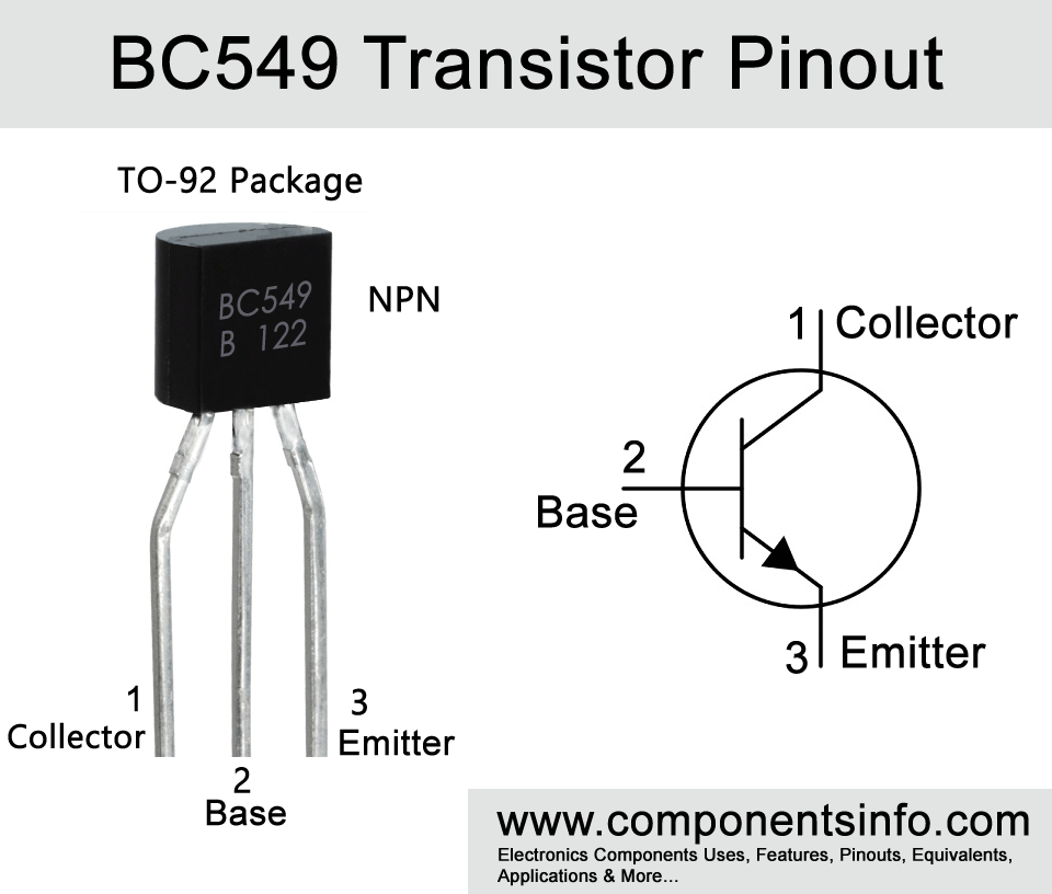
Not all BJTs or FETs have the same pinout corresponding to flat side orientation, some could be CBE or EBC left to right some even have strange pinouts with C in the centre the same applies to FETs it could be DGS, SGD or GSD etc
Unfortunately there is no standard pinout between manufacturers you should always go by the datasheet or Google for transistor pinout e.g. 2Nxxx pinout
You can also buy cheap transistor testers or a Peak Atlas DCA55 or 75 that will tell you a transistors pinout and other information
BillyModeratorPost some nice clear images Giovanni
So that all component values and orientation can be clearly seen and wiring traced
It’s very easy to not see something even if you’ve checked and checked again
BillyModeratorWhat transistors did you get with the kit I know musikding either send 5952s or 5457s which have opposite pinouts
BillyModeratorEasily done
500 pedals built and my latest I put in to out and visa versa
Saying that it was top mounted jacks I always side mount so that’s my excuse haha
BillyModeratorI think the BC549 pinout is opposite the 2N5088
BillyModeratorMay just be the light but your 100K resistors R9, 14 and 21 look like they have a grey band instead of orange as I say might just be reflecting light
Your transistor voltages are way off are you sure they’re correctly orientated is it 2N5088s you’re using
BillyModeratorWhat’s your voltage at Q2 collector
BillyModeratorGreat looking build far better than my first few that’s for sure
Looks excellent indeed
BillyModeratorIf you’ve got a multimeter take voltages on the transistor pins
Pinout like this
Here’s a PDF for an audio probe
https://drive.google.com/file/d/1T9OsJ0riQhm1QFWPfNQ5q5guikuFKDRN/view?usp=drivesdk
BillyModeratorMay not be the transistors post the transistor voltages that may give us an idea
Some of your transistor solder joints do look as if they lack solder try reflowing those joints hold your iron on the joints for 4 seconds until you see a nice pool of solder making sure you get a good connection between transistor pin and solder pad allow each pin to cool before doing the next one
I’d wait until you know what it is before changing anything it could be something simple like a dry solder joint
Do you have an audio probe
BillyModerator*edit
Eric’s correct
If using a common anode bi colour LED connect S4 and 6 to the two outer LED pads on the 3PDT pcb
As long as you ground the 3PDT pcb S5 will be fine left unconnected
Apologies! for some reason I was thinking LED connected to 3PDT pcb even though you clearly say it’s on the main pcb
BillyModeratorThere are a few solder joints that visually look dry some also look like the solder hasn’t flowed properly
Before reflowing joints you’re better trying to find where your problem lies
Post your transistor voltages that may help narrow it down
Hopefully you got your J201s from Barry which will guarantee their good
In your video it doesn’t sound like you’re getting much drive did you have gain maxed?
BillyModeratorCheck the LED ground connections sounds like your LED isn’t breaking it’s ground connection when switched
7K5 won’t make any difference I’d assume it’s just an easier value to find compared to 7K9
BillyModeratorDo you get effect but just at low volume
If that’s the case I’d start with reflowing the pot solder lugs especially volume lug 2 and treble lugs 2 and 3 some of the pot solder joints look like they may be dry
-
AuthorPosts