@barry
Forum Replies Created
-
AuthorPosts
-
 BarryKeymaster
That looks amazing. The extra pads came in handy. Thanks for the share.
BarryKeymasterExcellent I am glad you got it sorted out. Yes I think the Sriracha sounds amazing.
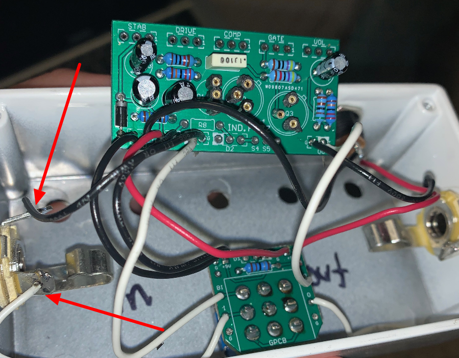
BarryKeymasterI will need to see photos of the changes and both In and Out Jacks.
There could have been more than the one issue I noticed. Basically I need to recheck all the off-board wiring since that is what would cause a mute pedal.
BarryKeymasterThis would be an easy way to fix.
1. Remove wire from Main Board Ground to 3PDT Board +9v pad altogether (see Red X 1) and forget about it.
2. Remove wire from Output Jack Sleeve where it connects to the 3PDT board (See red X 2) and resolder it to a fresh ground pad in the OUT box directly above the T pad on the main board pointed at with blue & white arrow. This is another extra ground.
That is it.
Many ways to accomplish the same thing: For example you could do the same maneuver with the Input Jack Sleeve wire and connect it to the IN box Ground Main Board if that seams easier for you. Those are the easiest ways needing only one point of solder work.
BarryKeymasterThere are many grounds. If that is the new V5 3PDT wiring board there should be a +9v symbol silk screened directly below the pad. If it says 9v then it is not a ground.
The old v4 boards show all three Ground pads labeled and grouped together.
For convenience and much neater wiring options as well as the lack of a need for 6 overall Ground pads we added another 9v pad (square) to the left side of the newer v5 boards as seen below:
At any rate it is an easy fix since you still have spare grounds (G) to use.
BarryKeymasterThanks for the pics.
This photo shows a 9v pad on the 3PDT wiring board going to ground on the main board.
You need to share a common ground to the Main Board from some point.
BarryKeymasterIt is still a wiring issue. We need better photos to be able to check everything.
Or use this guide:
BarryKeymasterAlso I believe your LED in the 3PDT Wiring board is wired to give you an LED light when the pedal is off. The cathode should connect to the Non-white pad for Active status.
BarryKeymasterIt appears to be wired correctly. I would look closely at the Input Jack as there are many wires that appear to be in the way when inserting your guitar cable. Also that said be sure your cables are both working and only use two good cables and one pedal for testing.
I would move wires out of the way so they will not get caught up with the guitar cable and also you may have to rotate the Jack slightly so that when you insert the Guitar Cable so that it does not short against the enclosure.
I would retest that you have good connections with all off-board wiring. Tug on them a bit to make sure they are not just hanging by a thread.
The orientations of the Electrolytic caps are fine and the IC’s as well.
Here is the Ancestral Build Doc for convenience for anyone else helping out.
BarryKeymasterI would use a Buff N Blend.
BarryKeymasterThis is a Tonmann design and he used the RG Keen information to help design the board 11 years ago however since Tonmann is no longer with us that will actually be the best explanation not having him around to put a fine point on it.
That said it works great and sounds great. Give it a go.
BarryKeymasterReverse these two wires.
See Billy’s post above for why:
BarryKeymasterI am glad you got it working.
I notice that the wiring diagram doesn’t show the extra mandatory ground wire and I think it should. I will fix that. There are notes in the build doc pointing to using both ground pads on the Vibe.
Right below the main schematic image on page 2 is this:
Build Notes: *There are (two ground pads), G & GND.Both ground pads must be wired to ground for the circuit to function. Connect both directly to the power supply ground for optimal noise free performance.
Anyway I wanted to mention that so other folks did not think the ground pad was literally missing.
BarryKeymasterBarryKeymasterVery nice job and thanks for the share.
BarryKeymasterBarryKeymasterThe voltages are correct. Read the Technology of the Fuzz Face article by R.G. Keen.
-
AuthorPosts