@barry
Forum Replies Created
-
AuthorPosts
-
 BarryKeymaster
@Barry. 7-28-2018, I had a similar view from RRA helluva show: Marcus King, Drive By Truckers, and Tedeschi-Trucks Band.
What a coincidence, just a few weeks apart. I really had a great time there and checked a bucket list item.
I was at the Umphrey’s McGee show and that video above was the opening act The Record Company which was a pleasant surprise.
BarryKeymasterYeah, and he said Red Rocks.
Visiting with Wilkie in Colorado July 7 2018.
BarryKeymasterThat is a very good idea to get your feet wet.
That said, take your time and digest everything while you wait. Study text and build photos etc..
BarryKeymaster“After all of the components my biggest question is what side of the PCB is the top and/or bottom.”
I answered that in the first paragraph of my previous reply and covered several other very important details you’re going to need to know before starting.
The photos in the Beginners Pedal Building Guide, along with the accompanying text on Page 2 + 3, show which side the components are inserted from and which side you solder (with all the leads sticking out).
The red text indicates hyperlinks that need to be viewed, if that wasn’t apparent. There are several of them in my previous answer, and they provide additional information that fully explains what you need to know.
I put quite a bit of time into writing my previous reply, so I’d really encourage you to go through it thoroughly before starting the build and view all of the hyperlinks. For example, the two builder-submitted Zoso Tone builds, each with build photos, the Resistor Chart, Capacitor Code Chart, Beginners Guide to Components, and more are all included in my previous reply with direct links. Going through this information first will answer most of the basic questions that will come up along the way and, most importantly, help prevent many of the common mistakes.
We cannot guarantee anyone a successful build, as that ultimately comes down to the builder, but I have given you what you need to put the odds of success in your favor.
BarryKeymaster@ Jason: I have never considered GBI40M. I will look into that.
With regards to Bat41 my personal favorite application for those was in the DumbleTone. I was pleasantly surprised by the result.
I will wait for some people to try 1N5817 in place of Germanium like 1N34A before adding anything because I don’t want to spoil the party with my interpretation. Also, imagine having 1N5817 in place of 1N914 in a Muff circuit 😉
BarryKeymasterHi and welcome,
I see you are a beginner. It is definitely better to ask questions than to just go for it and hope for the best.
As previously pointed out, it will require some reading. Fortunately, everything you need to know is here. Once you understand the basics, you will discover that the BOM in each build document, together with the silkscreen on the matching PCB, gives you everything you need to correctly place and solder the components and finish your build even without understanding a schematic.
Once you learn how to do one build, the rest are basically the same. You should still look at the schematic as you learn. Think of it as a flow from Input to Output, with everything you need in between and showing how all of the individual components are connected to each other. Start by following the signal path, and as you learn what each component does, the schematic will gradually begin to make sense.
The build documents assume you have this basic knowledge because the foundational information is covered in the Guides Page rather than repeated in every build document, keeping the individual build documents focused on the specific project.
Since you’re uncertain about how to install the components, go to the Guides Page and scroll down past the list of Build Documents to the Must Read Build Guides section. Look for the guide called Beginners Pedal Building Guide. I’ve linked it here for convenience, but I also recommend getting familiar with everything on the Guides Page because there is a lot of useful information there.
The guides are older and don’t specifically cover the NostalgiTone line of PCBs, but the basic information still applies and should answer many of your questions. NostalgiTone also makes the wiring process considerably easier by using its own wiring boards and ribbon cables, eliminating much of the complicated wiring and noisy “wiring spaghetti” that can be involved with traditional pedal builds.
As for parts, you not only need to know that R stands for resistor and C stands for capacitor, you also need to understand the values and types of components required so you purchase the correct parts. For example, in the Luna Fuzz portion of your build, R4 indicates a resistor value of 10K, which means 10,000 Ohms. R5 calls for 100R, where the R means Ohms, not K Ohms. There is a very big difference between 100 Ohms and 100K Ohms, so it’s important to understand these markings before ordering your parts.
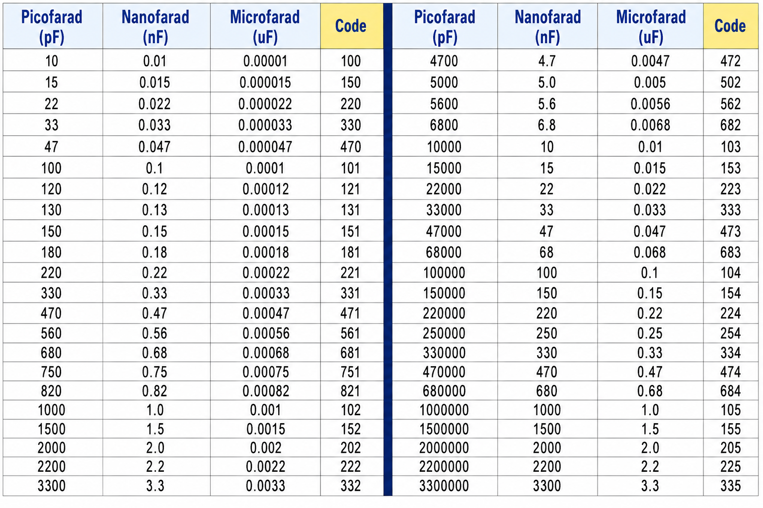
Pedal-sized resistors are almost always 1/4 watt. You can often find 1/4-watt metal film resistor kits on Amazon or eBay with a 1% tolerance (the blue resistors with five color bands), although resistor kits will not contain every value you will need. To help you learn how resistor color bands correspond to their values, go back to the Guides Page and look for the Full Color, High Resolution Resistor Chart and this handy Capacitor Code chart. I’ve linked them here for convenience, but again, take some time to look through the other guides in this section as well.
At this point, many of your questions will have already been answered, but there is much more to learn.
Capacitors come in many different sizes and materials, and some can be surprisingly large. You can learn more about them by going back to the Guides Page and reviewing the Beginners Guide to Components. This document is older and fairly extensive, but it contains a lot of valuable information. For now, you can go directly to the Capacitors section and concentrate on the information you will need for pedal building.
For example, if a capacitor in the BOM calls for a value in pF, which stands for picofarad, it will typically be one of the small orange ceramic disc capacitors. Most builds will have one or more of these. You can also identify them by looking at the PCB silkscreen, since the component outline will be a smaller box. This outline represents the part footprint and shows you the physical size and lead spacing the PCB was designed for.
Another very common type is the polyester film or box capacitor. Here, you need to pay attention not only to the capacitance value but also to the physical dimensions. The voltage rating can give you a good indication of the size; I generally look for 63V or 100V versions at most. You should also check the specifications or datasheet to make sure the capacitor has a 5mm lead spread. Most of our PCBs use a standard 5mm lead spread for film and box capacitors. You can also find convenient assorted kits containing many of the common values.
Another type you may encounter is MMLC (multilayer monolithic ceramic) capacitors. These are typically inexpensive, commonly available with a 5mm lead spread, and can often be purchased in assorted value kits. They are the yellow capacitors shown in the Beginners Pedal Building Guide. These can be used in place of polyester film or box-type capacitors as well as many of the pF (picofarad) values though you will need to pre-bend the 5mm leads to fit. When purchasing be sure they are specifically MMLC (multilayer monolithic ceramic) capacitors and never use Tantalum capacitors which are polarized and must be installed in the correct orientation.
When you see a capacitor in the BOM with a uF (microfarad) value, it will typically be an electrolytic capacitor. These are polarized, so they must be installed in the correct orientation. The capacitor itself will have polarity markings, and the PCB silkscreen will show a + next to the appropriate pad. Always pay attention to both.
You also need to consider the capacitor’s voltage rating. For these pedal builds, I typically use 25V to 63V electrolytic capacitors. Avoid using capacitors rated below 18V, since some pedal builders use 12V or 18V power supplies on circuits that can safely accommodate the higher voltage in order to gain additional headroom. Using a capacitor with too low a voltage rating can cause it to fail if the voltage across it exceeds its rating. Always check the component specifications or datasheet when you’re unsure. You can refer back to the Beginners Guide to Components for more information. You may also find assorted electrolytic capacitor kits, but these can be harder to find in the smaller sizes commonly used in pedal builds. Pay attention to the physical size and lead spacing as well. The electrolytic footprints used on our PCBs are typically 5mm or 6.3mm in diameter with 2.5mm lead spacing, depending on the component. Always check the PCB silkscreen and the component specifications before ordering to make sure the capacitor will physically fit the footprint. There are a decent amount of usable ones in this KIT but 10v are useless in pedals. 16v are fine as long as you stick with a 9v power supply.
The one exception to the uF = electrolytic rule could be a value such as 1uF. A 1uF capacitor may be an electrolytic, but it can also be a film, box, or MMLC capacitor depending on the circuit. The PCB silkscreen can help you identify which type is required: box/film capacitors generally have a rectangular footprint, while electrolytic capacitors have a circular footprint and a + marking for polarity. Always check the BOM and PCB before purchasing the part.
For the potentiometers, you will need 16mm right-angle PCB-mount potentiometers with a short solder legs. Do not use the long-leg versions.
You may also see “Trim” or “Trimmer” in the BOM. For these builds, look for 3362P Bournes trimmers. A trimmer is a small adjustable potentiometer used to set a circuit value during setup or calibration. My PCBs have an extra set of pads that will accommodate those or an RM-065 type spacing. You just drop them in which ever way they fit.
Some people prefer to avoid sourcing individual components altogether and simply pay more for a complete kit. It really depends on the person and how you prefer to approach your builds. While the assorted resistor and capacitor kits I suggested can cover many of the common parts you will need, they will not contain every resistor and capacitor value required for every build, so you will still need to source some values separately. You will also need to source parts such as trimmers, transistors, IC chips, switches, potentiometers, enclosures, and other components not included in the assortment kits. For those parts, there are several DIY pedal suppliers such as Small Bear, Stompboxparts, Lovemyswitches, and Amplified Parts where you can find what you need.
I do not sell kits myself but Small Bear and PedalPartsandKits do in the USA for which I supply them with the PCBs for.
Now that we have covered resistors, capacitors, and the Must Read Build Guides on the Guides Page, that leaves Q for transistors and D for diodes, both of which will have a specific part number or value listed in the BOM. For this build, you will also need two 3PDT footswitches and one ON/ON toggle switch, preferably with a short bat.
I would not proceed with the build until you are comfortable with this basic information and have ordered and verified the correct parts. Before soldering, physically compare your components with the PCB to make sure they are the correct size and match the silkscreen footprints.
You do not need a PCB holder to solder, but if you are working without one, it is especially helpful to install the components from shortest to tallest. Start with the resistors, followed by the 1N5817 diode, small pF ceramic capacitors, IC sockets or ICs, film/box capacitors, and finally the electrolytic capacitors. This makes things easier when you turn the PCB over for soldering.
Take your time and make sure each component is seated neatly against the PCB before soldering. Avoid excessive heat on the pads, and don’t rush the soldering process. Personally, I also use a small amount of flux when soldering switches and off-board components, as it helps produce clean, reliable solder joints.
As mentioned at the beginning it may be helpful is seeing an actual completed build from the Show Off Your Build section. Here is one Zoso Tone build and here is alternate Zoso Tone build that you can use as a visual reference. Looking at other people’s completed builds can help you understand how the components should look once installed and how everything fits together. This is in no way a substitute for reading the Guides I have recommended above, but it can be a very useful reference once you understand the basics.
And finally, don’t be afraid to ask questions here. This is my forum, not Twitter or Facebook. You are not going to get flamed for being a beginner or for asking questions. We were all beginners at some point, and I’d much rather have you ask a question than damage your PCB because you were afraid to ask. The only thing that I personally ask is that you do some reading first and then ask when you still aren’t sure, that’s what the forum is here for.
BarryKeymasterThe standard biasing for any non-fuzz would be half the supply, so 4.5v to 5v is what you want for proper operation.
BarryKeymasterVery nice, and it is always excellent IMO to get the kids involved.
BarryKeymasterI’ve been thinking a little more about the 1N34A vs. 1N5817 comparison. The forward voltage difference between the two really isn’t all that great, which the chart and datasheets both confirm.
Looking at the I/V curves, there does appear to be a difference in both where they begin to conduct and the shape of the “knee” as they transition into conduction. What I’m really curious about is how significant those differences actually are when the diodes are being used for clipping in a pedal circuit.
The reason I am curious is because Germanium Diodes are much harder to come by and expensive while the 1N5817 is readily available and affordable.
If the 1N5817 can provide suitable clipping characteristics despite the differences in its I/V curve and knee, I think the real question is whether those differences are significant enough to make the 1N34A audibly preferable, or whether the 1N5817 would make a perfectly suitable and much more readily available replacement. And if there is an audible difference, how noticeable is it in a real-world playing situation if it requires careful A/B switching to hear in the first place?
Reference: Circuits Journal — Analysis of nonlinear distortion in diode-based clipping circuits
This study includes measurements of both 1N34A germanium and 1N5817 Schottky diodes in clipping applications and discusses differences in their knee characteristics and resulting distortion.
The most notable quote from the above article says, “Germanium diodes (1N34A) demonstrated softer knee characteristics with 0.31 V forward voltage, yielding more gradual distortion onset preferred for musical applications. Schottky devices (1N5817) provided the lowest threshold at 0.24 V with intermediate distortion characteristics.”
Again, I am just trying to get some outside opinions to see how much of an audible difference there really is and whether the 1N5817 could be used as a substitute moving forward. I have tested this on my own using my DPDT wiring board with Germanium on one side and 1N5817 on the other in a Distortion+ style circuit, but I would love to hear other opinions first before revealing my results.
I don’t think there are any right or wrong answers here, and I would also be interested to hear if I am missing any other factors that should be considered. Let me know what you think.
BarryKeymaster“I didn’t expect to break the internet with my post”
That said, as the owner of the site, I have access to information that shows me exactly how many people are stopping by and reading these posts, and I bet you would be surprised by the numbers. The biggest difference between today and 10+ years ago is that people used to take the time to comment, ask questions, and share their experiences. That’s something I really miss.
For example, this thread posted by BigO about my new guide, How Gain, Headroom & Clipping Shape Your Tone, has already had 1,543 unique visits, most of them from members here, but only two comments. Yours and mine.
While I’m certainly glad people are reading it, I’d love to see more of the discussion and interaction that used to be such a big part of the forum.
Let me look over your answer regarding the 1N34A vs. 1N5817 analysis, and I’ll post later on that.
I appreciate your post, interest, and participation.
BarryKeymasterThis is excellent, BRD, but I was hoping this wouldn’t just be a conversation between you and I. 😄
This is one of the most advantageous areas for DIYers to explore and typically an easy modification. More importantly, when you understand what is actually going on, you can get exactly what you want instead of randomly guessing at different clipping options.
There’s a lot to discuss here, so maybe some people will jump in with some thoughts, input, questions, or curiosities and get the conversation going.
Here’s a question of my own: How much do you think the difference between the softer knee of a 1N34A and the harder knee of a 1N5817 affects the actual clipping character when substituting one for the other? Being that their forward voltages are fairly close, would you expect the difference in the way they clip to be noticeable in the sound?
August 18, 2026 at 1:01 pm in reply to: New Guide: How Gain, Headroom & Clipping Shape Your Tone #40333BarryKeymasterThanks, @brd. I spent a good deal of time on this and had to make some decisions about what to include and what to leave out. My goal was to keep it easy to understand for anyone, while still providing enough information to help take them to the next level.
August 12, 2026 at 11:57 pm in reply to: New Guide: How Gain, Headroom & Clipping Shape Your Tone #40287BarryKeymasterI hope people are finding this new guide useful.
BarryKeymasterWow, OK. That was some typo.
Several conflicting reports and I should have looked closer at the symbol and not just the text above it.
I got it sorted now and thanks for pointing it out. It is a TL071 and not TL072.
I have updated the Build Document.
BarryKeymasterWow, OK. That was some typo.
Several conflicting reports and I should have looked closer at the symbol and not just the text above it.
I got it sorted now and thanks for pointing it out. It is a TL071 and not TL072.
I have updated the Build Document.
BarryKeymasterAlternatively, to the AmpEQ sitting in front of the main amplifier preamp (guitar -> AmpEQ -> guitar amp input), which creates a subtle overdrive perfect for a classic Stones, Faces, or Black Crowes tone you can try using the amplifier effects loop.
For your suggested “Sculptor” setup, I encourage builders to create a dual pedal combining the Sonic Bloom and AmpEQ, then run this dual pedal directly in the amplifier’s effects loop to completely bypass the preamp. This provides massive EQ and tone enhancement without creating any unwanted clipping, allowing gigging musicians to make fast EQ adjustments for different venues.
Both implementations work extremely well but I wanted to mention the effects loop option for that reason.
August 5, 2026 at 6:34 pm in reply to: New Guide: How Gain, Headroom & Clipping Shape Your Tone #40198BarryKeymasterThanks Big O.
It’s available on the Guides Page but I will place it here for convenience.
-
AuthorPosts