@barry
Forum Replies Created
-
AuthorPosts
-
 BarryKeymaster
It is the same. Only cosmetic differences.
If you want to check the numbering it is here: Swah OLD v3B
There is an OLD v3 (no B) which has not been available in 9 years that required a single jumper and that was the only difference between v3 and v3B
March 30, 2025 at 9:31 pm in reply to: LEDs Will Not Work On NostalgiTone Dual Combo Creator (solved) #35806BarryKeymasterThe only thing I can think of from your description is from the Build Document under Build Notes #2.
2. Since the Dual PCB offers an additional LED Status location, you can choose your preferred setup. Whichever option you pick, solder a small jumper on the unused LED pads.
If that is not it I am going to have to see pictures with a small description or markup for each photo point.
March 26, 2025 at 5:15 pm in reply to: Printed Enclosure Bundles of NostalgiTone Space Modulator and Doom Prophet #35784BarryKeymasterThanks so much for your kind words! I put a lot of time and work into preparing each enclosure order, sourcing high-quality bundle components, as well as carefully packing everything in a timely manner so it arrives safely. It’s great to hear that you appreciate those details!
For anyone who missed out on Round 1, Round 2 of the NostalgiTone Enclosure Bundle Deals is live now! This is another chance to grab these combos while they’re available.
I’ll do my best to continue offering these bundles from time to time as long as there’s enough interest. Thanks again for your support, and happy building!
March 26, 2025 at 11:50 am in reply to: Is there a possibility of more Tayda drill templates? #35779BarryKeymasterUnfortunately, the old Legacy PCBs can’t be directly converted to a Tayda-compatible format or they would have all been done. They were originally designed on an inch grid that was also off-center, meaning everything needs to be realigned to the origin and converted. Additionally, since the potentiometers weren’t placed with their shafts as the center point, their drill locations must be manually adjusted, adding to the complexity.
BarryKeymasterThe LED is a clipping Diode. In this case providing asymmetrical clipping. So between the LED and the assymetrical clipping the idea is that it provides a more “Tube Amp” like clipping tone.
The B1M Gain pot will affect the Gain.
BarryKeymasterI wanted to double-check a few things before making a suggestion.
The resistor values look good, so there’s nothing to adjust there.
If you swap the Gain pot for a B1M, you’ll get more available gain. However, keep in mind that maxing everything out could introduce some noise or potential squealing.
BarryKeymasterPlease post clear pictures of the top of the PCB that shows resistor band colors.
BarryKeymaster“I think this happens sometimes in the manufacturing of PCB’s.”
A trace not connecting properly to a pad could be but not an entire length of trace missing from the PCB, masking and all.
The PCBs are fine as shown above.
BarryKeymasterThat is gorgeous! Thanks for sharing.
BarryKeymasterI’m glad you were able to figure it out!
I’m honestly perplexed by the issue, as many of these PCBs have been successfully built and shared here, including by myself. I’ve also sold quite a few finished builds without encountering this problem. While I absolutely believe your experience, I want to reassure others that this appears to be a rare, one-off occurrence.
To clarify, I took a picture of the back of the PCB I sell, and you can clearly see the trace.
So again, I am sorry you had an issue but happy you figured it out.
BarryKeymasterThanks brd. Not in my wheelhouse.
BarryKeymasterI am not 100% sure what you are trying to do.
I would personally build out the Sonic Tonic as a pedal and then insert it into the channel of the mixer or go straight to the pedal from the guitar and output to amplifier. The effect will be good for both of the final mixed signals.
BarryKeymasterThat seems fine.
Next I would check foot switch connection pads to my main board connector pads with your DMM in continuity mode. Especially since that is an area you had to kludge a bit. I would put it on beep and check between pads to make sure there is a true connection.
If that doesn’t help I would start re-flowing solder joints all along the back of the main PCB for the entire OD section (every single pad). Just reheat the pad and let the solder flow for a moment. Have some extra solder handy if needed. It is really a very common problem to have a cold solder joint.
Be careful not to bend the potentiometers back and forth too many times or you will damage the leads. You will likely need to re-flow those pads as well after your through re-flowing all of the component pads.
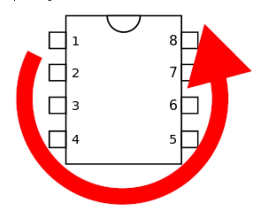
BarryKeymasterProvide DC voltage readings at all 8 pins of The TL072 in the proper orientation.
I will assume that none of those yellow capacitors are Tantalum which have a small polarity imprint.
BarryKeymasterI would just feel different.
BarryKeymasterTechnically the Stage 3 can go before or after the compressor to solve the phase problem. Due to the nature of a compressor I would not place the Boost in front of it. I would rather have the Stage 3 enhancing the tone following the compressor instead of coloring it (while potentially adding noise) by placing the Boost it in front of it.
BarryKeymasterThis circuit is based on the Ross Compressor so it will invert the phase when used in a parallel situation which is why I mentioned the Paramix. That said if you insert an additional (single) stage circuit in series after the compressor like the Stage 3 Booster then that problem is solved.
I would try the simple Mod suggestions first though as you may be fine with that.
-
AuthorPosts