@barry
Forum Replies Created
-
AuthorPosts
-
August 9, 2025 at 8:29 pm in reply to: NostalgiTone Analog Chorus: Premium CE-2 Design now available #36992
 BarryKeymaster
I was ready to give you credit for reading the manual — I figured you might be adrift in the sea of adjectives guitar pedals love to use.
August 8, 2025 at 3:07 pm in reply to: NostalgiTone Analog Chorus: Premium CE-2 Design now available #36976BarryKeymasterIn the build document that would be referred to as the Intensity Mod.
Intensity Mod: replace C21 (47pF) with 68pF to 100pF to increase intensity.
Have fun!
BarryKeymasterYou can use a 1k Trimmer on the Gypsy Fuzz.
BarryKeymasterSorry that is a typo.
The build document has been updated.https://stompboxparts.com/integrated-circuits-ics-/v3102d—bbd-clock-ic/
BarryKeymasterThat looks fantastic, and thanks for sharing!
I love the color choice but mostly adding the available Mods. They fit very nicely in there.
Oh and don’t forget the order switching…
Check out this BLOG for details on this Dual Combo and the benefits of Order Switching.
https://pedalplayers.com/klon-before-or-after-bluesbreaker/
available for purchase here: https://guitarpcb.com/product/nostalgitone-john-mayer-tribute/
August 1, 2025 at 2:07 pm in reply to: Anxiety Disorder too distorted – Volume pot not working #36939BarryKeymasterCheck and verify the pinout configuration of the Mosfets you are using because sometimes they can be different between manufacturers. See this article for what I am referring to: https://www.muzique.com/news/mosfet-pin-configurations/
You can also check your voltages of the Mosfets as well as the Opamp.
August 1, 2025 at 10:43 am in reply to: Anxiety Disorder too distorted – Volume pot not working #36936BarryKeymaster+1 Billy
BarryKeymasterThat looks fantastic and thanks for sharing.
Having more is always better. Gain Mapping is a way of life.
BarryKeymasterIt is a fairly simple mod so the first thing I would do is verify continuity from +9v to the LED as well as the Ground with your DMM.
also the solder joints are very close to shorting on the enclosure. might not be an issue but worth a look.
The old build doc is on the Guides Page – Top Link:
https://guitarpcb.com/wp-content/uploads/2018/06/BD_Dr-Phybes.pdf
BarryKeymasterPictures may be able to help?
Not much to go on otherwise.
BarryKeymasterNice execution!
BarryKeymasterThe 2N5089 is likely a closer match, as it offers a higher gain similar to the MPSA18.
The ones I sell typically test around 800 hFE.
If you can find a pair in that similar range, feel free to socket and experiment with them.
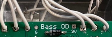
BarryKeymaster@MathU41 – His description goes seems to go well beyond the issues you reported, so I feel there’s something wrong beyond a tweak. We just need to identify it step by step. I’ll wait for his complete report including voltages before offering suggestions for his build.
As for your specific case, this circuit is designed to overdrive a bass amplifier, which can cause unwanted distortion and artifacts when used with a guitar amp. If you’re planning to use it in a guitar setup, you’ll need to adjust several capacitors to prevent excessive low-frequency content from overwhelming the amp’s preamp or speaker.
If the issue is coming from hot pickups — whether passive or active — the easiest way to tame the gain is by increasing the source resistors (R3, R6, and R9).
Try 4.7kΩ to start. If that’s not enough, you can bump them up to 6.8kΩ or even 10kΩ.
More resistance means less gain, but it doesn’t mess with the tone or how the stage is biased. You’ll get the same overall character, just less drive.
If everything else in Franz’s build checks out, I’d make the same suggestion.
Guitar Mod Tip:
Change C1 from 22uF to 100n MLCC type capacitor (for easy fit) to cut excess bass at the input. It tightens up the tone and keeps your amp from getting overloaded—great for a cleaner low end without affecting mids or highs.C1 Capacitor Value and Bass Response (Assumes R1 = 33kΩ):
-
22µF (stock) electrolytic:
0.22 Hz cutoff — passes all bass frequencies. -
1µF electrolytic:
4.8 Hz cutoff — slight bass cut, still sounds full. -
100nF MLCC:
48 Hz cutoff — noticeably tighter low end. Good for taming boominess. -
22nF MLCC:
219 Hz cutoff — heavy bass cut. Full, Bright Guitar Tone
Note that I suggest MLCC type which is for easier fit in the electrolytic package on the PCB. You can also just bend the leads accordingly on whatever types of capacitors you have handy.
Let me know if that helps.
BarryKeymasterHi Franz,
Your issue may not be the same as the one in this topic which is why we prefer a separate thread. His problem was from using a tiny hand held practice amplifier meant for standard guitar.
That said, I noticed a couple of things. As a result I have several questions, and need exact voltages to move forward.
-
Your potentiometers aren’t soldered directly to the PCB, which they should be. One, or two solder pads also don’t appear fully filled, which can cause poor connections. Since the pots are mounted this way, is there anything insulating them from the solder side of the PCB to avoid shorts?
- Also since you hand wired the potentiometers I was not able to verify from the photo that the square pad for each potis on the PCB was connected to Lug one of each respective potentiometer.
**********************************************
Be sure your transistors are seated firmly and not moving around loosely in the socket.
For proper troubleshooting, please provide the exact voltage readings for all three transistors, labeled like this:
Q1
D:
S:
G:Q2
D:
S:
G:Q3
D:
S:
G:- R11 serves as a lower limit for the output level, ensuring the volume does not fall below unity gain (bypass level). It does not contribute to any gain increase in the circuit. A 1k resistor is the correct value, and is specified in both the BOM and Schematic correctly. Either way it would not add Gain. I fixed the image with the “photo typo” on the last page.
- Please also let me know what amplifier you’re using. For accurate testing, be sure to run the pedal alone—no other pedals or gear in the signal chain—and use two known-good cables.
Keep in mind this project has been built successfully many times since its release in 2010. We also have video demos available that showcase a working version, so we’ll have to troubleshoot properly—we just need to go step by step.
This demo is from 4 years ago:
BarryKeymasterThat looks fantastic and thanks for sharing!
I am glad you like it.
BarryKeymasterThat looks fantastic — thanks for sharing!
I really appreciate the gut shot too — it’s great for showing how everything can fit neatly, even in a small enclosure.
BarryKeymasterCorrect — a stereo jack is only needed if you’re using a battery, which most builders skip.
You may want to relay that info to Klaus as well.
Looks like everything’s good now — enjoy!
-
-
AuthorPosts