Your Source for DIY Pedal PCBs and NostalgiTone! › GuitarPCB Forum › GuitarPCB Build Support › Bass OD – Too much drive.
- This topic has 13 replies, 4 voices, and was last updated 9 months, 2 weeks ago by
 koenichsound.
-
AuthorPosts
-
May 21, 2025 at 7:03 pm #36309MathU41Participant
So I built a Bass OD, and it seems to work horribly right.
With the drive turned to 0, it cuts out. Whatever, I don’t plan to have it turned on for no effect.
Then I can get to maybe 10% before it turns from ‘hair of drive’ to ‘cranked fuzz’.
Even with the bass volume rolled off, if any volume goes into it, I get sputtery, inarticulate grinding sounds, with notable ‘steps’ between slight drive to broken up and then a point where it sputters to even harsher noise.
I can’t blame the circuit, and apparently can’t blame my work (this time) because it’s definitely doing what it’s supposed to, just too much of it.
Currently it’s 3 J113s adjusted to 5.9v. No notable difference from 5.5v.
Does it work well enough to keep rolling those down under the suggested 5-6v? If not, I know the notes say to try different transistors, but I have no idea where anything stands on a ladder of gain.May 21, 2025 at 7:45 pm #36310BillyModeratorYes it’s definitely worth biasing the bottom drain pin to different voltages to see if you can get a sound you’re happy with I generally start around 4.5v and increase bias voltage
Are your pickups active or passive
Where did you get your transistors although J113s are still available in through hole package there are a lot of fake FETs around
May 21, 2025 at 8:09 pm #36312MathU41ParticipantAlright, first order of business: fiddle with the voltage, when I get a chance.
Passive pickups. A stock Ibanez GSRM20 and TMB30. Love these things.
I believe I got these ones here. No one’s immune from some supply chain shenanigans, but I trust this place and figure Barry would have found out if he got a bad batch.
Some things I’m willing to get from eBay or Amazon, but if it seems sketchy and I can’t do my research, I stick with a few known places.May 22, 2025 at 5:07 pm #36319MathU41ParticipantOkay, seem to be on the right track.
Down to 3.5v and have almost half the drive knob usable. Don’t know how much lower I can go, but I do still have a good bit of distance in the trimpots.
The adjustment is almost more of a blend than an amount. It’s more like ‘how much string sound is making it through the velcro.’ I’m sure some of it is because I don’t have my own proper bass amp; I’m running it through a guitar practice amp, usually with headphones.
And I’ll have to attach a few of my SMD J201s to their boards and try those out to compare.May 22, 2025 at 11:22 pm #36322BarryKeymaster4.5v should be your optimal voltage for the least amount of overdrive.
My transistors are always genuine as you mentioned.
I’m not entirely sure what you mean by “practice amp with headphones,” but I definitely recommend trying it through a standard bass amplifier. There are two unique demo videos on the shop page, and I was able to dial in a wide range of tones using a small 25-watt Orange Crush combo. That said, keep in mind this pedal is designed as an overdrive. From your description, it sounds like you may be overloading the preamp on your practice amp.
May 23, 2025 at 5:54 pm #36337MathU41ParticipantYeah, overloading this thing might be a genuine concern.
To be fair it was mostly bought for the space concerns, so I could have it in the work area, and it’s usually an almost respectable headphone passthrough . It actually manages a lot better than expected for guitar… I didn’t expect much.
It already struggles a little on bass, and I assume it’s just not designed for those frequencies.
I’ll be going back to the old 15-watt Fender once I’m done with repairs on that, and I’ve also been poking into the local pawn shops checking for actual bass amps.Anyway, adjustments have helped, I know this can work, and no components got called out, so I’m going to call the circuit good, box it, and tweak from there. I can always adjust trimpots or swap transistors in situ.
June 25, 2025 at 2:59 pm #36650koenichsoundParticipantHello. Franz here. First post!
Bought the Bass OD from musikding.de
I cannot get it sounding right at all. Tried biasing for the recommended voltage, tried Passive & Active PUs, In front of an Amp, into a DI etc.
It is way too loud. Volume control unusable. It is like shooting at my Audio Interface and breaking the preamp. Gain does not start at slight, even at 0, you can hear it cut through (some crosstalk) with full drive power. Dealing in more sounds like 100 broken amps in a row. That’s nowhere near usable. Checked the wiring, the components again and again. No improvement. Any idea how to tame the beast or what could be wrong?
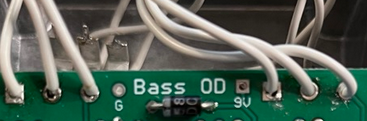
(btw. there is a mistake in the manual, section “populated board”: R11 shows as 33K Ohm, but in the schematics and parts table it is 1K Ohm. So I soldered it in wrong on my foto, but I tried also with R11 at 1K Ohm. Does not work either.
June 25, 2025 at 7:54 pm #36653BarryKeymasterHi Franz,
Your issue may not be the same as the one in this topic which is why we prefer a separate thread. His problem was from using a tiny hand held practice amplifier meant for standard guitar.
That said, I noticed a couple of things. As a result I have several questions, and need exact voltages to move forward.
-
Your potentiometers aren’t soldered directly to the PCB, which they should be. One, or two solder pads also don’t appear fully filled, which can cause poor connections. Since the pots are mounted this way, is there anything insulating them from the solder side of the PCB to avoid shorts?
- Also since you hand wired the potentiometers I was not able to verify from the photo that the square pad for each potis on the PCB was connected to Lug one of each respective potentiometer.
**********************************************
Be sure your transistors are seated firmly and not moving around loosely in the socket.
For proper troubleshooting, please provide the exact voltage readings for all three transistors, labeled like this:
Q1
D:
S:
G:Q2
D:
S:
G:Q3
D:
S:
G:- R11 serves as a lower limit for the output level, ensuring the volume does not fall below unity gain (bypass level). It does not contribute to any gain increase in the circuit. A 1k resistor is the correct value, and is specified in both the BOM and Schematic correctly. Either way it would not add Gain. I fixed the image with the “photo typo” on the last page.
- Please also let me know what amplifier you’re using. For accurate testing, be sure to run the pedal alone—no other pedals or gear in the signal chain—and use two known-good cables.
Keep in mind this project has been built successfully many times since its release in 2010. We also have video demos available that showcase a working version, so we’ll have to troubleshoot properly—we just need to go step by step.
This demo is from 4 years ago:
June 26, 2025 at 12:37 pm #36709MathU41ParticipantWell, at least part of my problem was the tiny amp. It still gets up there on my more proper one, but I have a bit of usable range and that one’s still built for a guitar. I haven’t had the wherewithal for further experimentation or an opportunity to buy a proper bass amp to verify yet but it’s certainly better than it was.
I do wish koenichsound luck here. Making sure everything’s matched up, firmly in place, and solder is holding fixes many, many problems, especially invisible ones.
June 26, 2025 at 1:20 pm #36710BarryKeymaster@MathU41 – His description goes seems to go well beyond the issues you reported, so I feel there’s something wrong beyond a tweak. We just need to identify it step by step. I’ll wait for his complete report including voltages before offering suggestions for his build.
As for your specific case, this circuit is designed to overdrive a bass amplifier, which can cause unwanted distortion and artifacts when used with a guitar amp. If you’re planning to use it in a guitar setup, you’ll need to adjust several capacitors to prevent excessive low-frequency content from overwhelming the amp’s preamp or speaker.
If the issue is coming from hot pickups — whether passive or active — the easiest way to tame the gain is by increasing the source resistors (R3, R6, and R9).
Try 4.7kΩ to start. If that’s not enough, you can bump them up to 6.8kΩ or even 10kΩ.
More resistance means less gain, but it doesn’t mess with the tone or how the stage is biased. You’ll get the same overall character, just less drive.
If everything else in Franz’s build checks out, I’d make the same suggestion.
Guitar Mod Tip:
Change C1 from 22uF to 100n MLCC type capacitor (for easy fit) to cut excess bass at the input. It tightens up the tone and keeps your amp from getting overloaded—great for a cleaner low end without affecting mids or highs.C1 Capacitor Value and Bass Response (Assumes R1 = 33kΩ):
-
22µF (stock) electrolytic:
0.22 Hz cutoff — passes all bass frequencies. -
1µF electrolytic:
4.8 Hz cutoff — slight bass cut, still sounds full. -
100nF MLCC:
48 Hz cutoff — noticeably tighter low end. Good for taming boominess. -
22nF MLCC:
219 Hz cutoff — heavy bass cut. Full, Bright Guitar Tone
Note that I suggest MLCC type which is for easier fit in the electrolytic package on the PCB. You can also just bend the leads accordingly on whatever types of capacitors you have handy.
Let me know if that helps.
June 26, 2025 at 4:01 pm #36711MathU41ParticipantBarry, I really appreciate that and I’m filing that for future reference. I’m not intending to use it for my guitar or through the guitar amp once I get a bass one, but I also don’t know just how hot the pickups in my basses actually are. This could be useful.
If it doesn’t work out as soon as I snag a proper bass amp, I’ll be tinkering here. Maybe I will anyway just for variety.
For the guitar, I have a range of other wonderful overdrives and distortions, thanks to you. 😀
That said, between basic troubleshooting and the suggestions here, I hope Franz’s problems clear up well.
August 26, 2025 at 6:12 pm #37161koenichsoundParticipantMissed the conversation and that you took time to reply. Sorry.
Playing a Fender Jazz Bass in the Hi-Z of an Apollo Interface into an Ampeg SVT simulation.
Tried It into a TC 500W head hooked to a 4×12 Hartke 10″ cab.When engaged, the signal jumps 21+ dB at lowest potentiometer settings. So it is driving whatever comes after it “heavily”. It’s not intended like this, or is it? You cannot play “clean” and then engage. It kills you instantly ^^
I wired the potentiometers temporarily until this pcb works haha. Lug1 of the Poti is connected to the square connector on the PCB.
Just measured (9V power supply):
Q1:
- D 5.87
- S 1.3
- G 0
Q2:
- D 5.81
- S 1.56
- G 0
Q3:
- D 5.67
- S 1.4
- G 0
August 26, 2025 at 9:48 pm #37167BarryKeymasterHere is the Mod I posted above:
August 27, 2025 at 5:05 pm #37181koenichsoundParticipantThanks Barry. Trying the 6.8k route to tame it for me.
-
-
AuthorPosts


- You must be logged in to reply to this topic.