Your Source for DIY Pedal PCBs and NostalgiTone! › GuitarPCB Forum › GuitarPCB Build Support › dsotm fuzz v4 not very fuzzy (solved)
- This topic has 6 replies, 3 voices, and was last updated 6 months, 1 week ago by
 Barry.
-
AuthorPosts
-
November 19, 2025 at 11:13 pm #37899Deebs3Participant
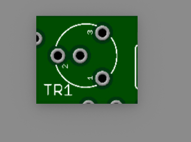
hi all, just built the dsotm fuzz v4 and it’s not very fuzzy. Into a clean amp it’s just starting to sound a bit fuzzy with all knobs on full and trimpot on max. I assume this is not normal, it sounds fine with boost behind it. I suspect the trimpot, it has 3 legs but 4 holes on the pcb, does leg 2 go into the hole numbered 2 or into the hole next to it? Perhaps this makes a big difference?, It’s impossible to see from other peoples builds because the pot covers the mounts. cheers.
November 19, 2025 at 11:24 pm #37900BillyModeratorThere are two holes for pin 2 both are connected by the trace you can see between them it’s to accommodate different styles of trimmer
Post some nice clear in focus images of your build so that all your component values and orientation can be clearly seen and offboard wiring traced
November 19, 2025 at 11:36 pm #37901Deebs3ParticipantThanks, yes i didn’t see the trace before, i’ll post some pics later after i double check everything, also R13 on the schematic and parts list is 100R but the coloured layout shows 100k, i assume the correct value is 100R which is what i used (and everyone else from what i can tell) , thanks for your help..
November 20, 2025 at 5:48 am #37902Deebs3ParticipantHey I found the prob, I used the wrong value for R5, don’t know why, and didnt check it because it is hidden behind a cap, huge fuzziness has been restored, cheers.
November 20, 2025 at 3:16 pm #37906BillyModeratorGlad you fixed it
I still on occasion solder in the wrong value and that’s after almost 20 years of building and knowing the colour band values off by heart
It’s very easily done
November 22, 2025 at 6:44 am #37911Deebs3ParticipantHey just for future reference, the reason I chose the wrong resistor value was the build pdf has a colour diagram of the layout and R5 and R13 are shown as 100k when the schematic and parts list shows them as 100R, the correct values. Cheers.
November 22, 2025 at 1:02 pm #37913BarryKeymasterSorry for the issue with the populated board image in the build document. I’ve removed that image. That was a very old and, in hindsight, bad idea — laying little resistor images on the PCB one at a time (as if you were soldering them) made it far too easy to introduce a photo typo. I stopped doing it a long time ago, but I missed this one.
This all happened while I was recovering from a stroke, and the image exercise was actually meant to help me regain my vision. While I always recommend following the BOM and schematic when building, I completely understand the temptation to use the photo. Thanks for catching it!
-
AuthorPosts
- You must be logged in to reply to this topic.