@barry
Forum Replies Created
-
AuthorPosts
-
 BarryKeymaster
Excellent build and thanks for posting.
Sometimes the simple solution is the best one. This is one of those circuits that always worked well with me regardless of guitar or amplifier and also is great to use in tandem with something else creating an additional tonal option.
BarryKeymasterVery Nice! Thanks for sharing!
BarryKeymasterAnother excellent build! Thanks for sharing.
BarryKeymasterAwesome build—thanks for sharing it! As the site owner, I can tell you lots of folks read these threads even though they don’t leave a comment. So even when it seems quiet, your post is getting plenty of eyes. Appreciate you posting and inspiring the community!
BarryKeymasterThat looks fantastic! Thanks for sharing.
BarryKeymasterTwo PMs were sent just now.
To summarize:
- RTN → TIP_OUT on the main PCB will read OPEN in bypass. That’s expected—the 3PDT only connects RTN <-> OUT when the effect is ON.
- The real pass-through check that should ALWAYS beep (regardless of ON/OFF) is the final hop from the last effect’s OUT₃ pad → TIP_OUT pad → output jack tip.
TEST (power OFF):
OUT₃ → TIP_OUT (main PCB pads) = beep
-
- If open: reflow both pads; if still open, add a tiny fly-wire OUT₃ → TIP_OUT on the PCB.
Jack TIP lug → actual tip of the inserted plug = beep
-
- If open: jack/plug seating or cable issue.
Bottom line: “RTN → TIP_OUT = no beep” in bypass is normal; failure on section C-4 (#3 OUT → Output jack TIP) points squarely to the final hop. Fixing OUT₃ <-> TIP_OUT <-> jack TIP will restore bypass and let the whole chain pass audio.
BarryKeymasterHere are some other quick check items:
With the pedal unpowered, TIP→TIP should still beep in full bypass. If it doesn’t, the fault is 100% in the bypass chain.
- Test inside the pedal first (unpowered, all bypassed).
If IN ↔ OUT beeps on the main-board pads, the pedal’s bypass path is good.
Now test the cables.
-
-
Plug one cable into IN, one into OUT; leave the far ends loose.
-
Meter tip→tip (free ends): must beep.
-
Meter sleeve→sleeve: must beep.
If either fails, it’s a bad cable or jack seating (scrape paint to bare metal around the jack holes).
-
-
Swap to two known-good TS instrument cables (no SilentPlug ends, etc) and retry.
Wiggle the plugs while metering—intermittents are common. -
If cables pass but there’s still no audio, re-check jack lugs with a plug inserted (tip of plug → wired TIP lug must beep). A wire on a switched or ring lug will kill pass-through just like a bad cable.
BarryKeymasterI suggest a reflow with close attention to the socket pin soldering
PT2399 IC5 all pins and both ends of R39, R40, R41, R42. Inspect under magnification for:
• hairline bridge to ground near pin 8,
• lifted pin-8 pad,
• check for properly seated IC into the socket and good socket solder joints
• the small film caps (C31/C32 on that node) only to GND (no stray solder whisker touching a trace).To be clear the voltage discrepancy is not going to cause all three circuits to not work so that is something else.
Here is a generic checklist to follow
A) Prove each switch board in place (power off)
For each effect (#1 → #3), with the footswitch OFF (bypass):
-
IN → OUT (on that effect’s main-board header): should beep.
-
SND → RTN: should beep.
Expected continuity
Switch OFF (bypass):
-
IN ↔ OUT = beep
-
SND ↔ RTN = beep
-
IN ↔ SND = open
-
RTN ↔ OUT = open
Switch ON (engaged):
-
IN ↔ SND = beep
-
RTN ↔ OUT = beep
-
IN ↔ OUT = open
-
SND ↔ RTN = open
If any step fails, reflow the switch lugs on that board and the 6 ribbon pads on both ends for that effect. One bad joint here will kill all audio.
B) Verify order
Still power off—check that each net lands on the same labeled pad at both ends:
-
Main IN pad ↔ wiring-board IN pad = beep
-
Main SND ↔ wiring SND = beep
-
Main LED ↔ wiring LED = beep
-
Main GND ↔ wiring GND = beep
-
Main RTN ↔ wiring RTN = beep
-
Main OUT ↔ wiring OUT = beep
C) Walk the full bypass bus, jack-to-jack (all three OFF)
-
Input jack TIP → Effect #1 IN = beep
-
#1 OUT → #2 IN = beep
-
#2 OUT → #3 IN = beep
-
#3 OUT → Output jack TIP = beep
The first hop that doesn’t beep is the break (wire, header, or that 3PDT board).
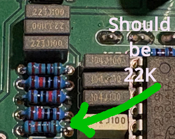
BarryKeymasterYour R42 resistor should be a 22k which is Red – Red – Black – Red – Brown.
Looking at the image provided it does not appear to be that. Further that would absolutely skew the PT2399’s bias/RC network around pins 5–8 and would produce exactly the odd readings you saw (pin-6 too high ~Vref, pin-8 too low).
While the resistor in question above could technically be the Red stripes they do not match the brightness of Red of the surrounding resistors. You will have to decide.
BarryKeymasterUpdate: PT2399 at IC 2 looks good, however compare the IC 2 voltages with the voltages at IC5 PT2399 and you will see Pin 6 = 2.83V (too high). Also Pin 8 is too low at .69v
You can recheck if you think it was a measurement error.
As a fast test, swap the PT2399s; if the bad readings stay with the PCB position, it’s the surrounding parts, not the IC and vice versa.
The Reverb brick looks fine. This will take a while…
BarryKeymasterJust to confirm: you’re getting no signal at all—even with all three circuits in bypass—and when you test them one at a time (engage one, then return it to bypass before trying the next), there’s still no signal. Is that correct?
BarryKeymasterI wanted to make sure you got my message above regarding the minimum 100mA power supply requirement.
Your build can be perfect but nothing will work.
BarryKeymasterWithout clear photos or voltage readings it’s a bit like trying to help a car that won’t start over the phone, we can definitely try, but we’ll need a few basics checked first:
-
Voltage regulators
-
Please confirm the exact part numbers (e.g., 78L05, L78L05, etc.).
-
Double-check Datasheet orientation: some regulators have reversed pinouts depending on package/brand. It’s surprisingly easy to install all three backwards if the silkscreen and part don’t match.
-
-
IC orientation
-
Verify every IC is seated the right way (notch/dot matches the board outline). There are a few in this build, so please check each one.
-
-
Trimmers
-
Set all three volume trimmers to 12 o’clock (Noon) as a starting point.
-
If that doesn’t get you there, the quickest way to locate the fault is an audio probe to trace the signal path and find exactly where it disappears.
Since the problem affects all three circuits, focus on parts common to all of them: the three voltage regulators (verify part numbers and orientation) and anything else that comes in threes—like the 3PDT footswitches. Make sure each switch is latching, not momentary. Each circuit contains a 4558 IC so make sure of orientation.
Alternatively, please provide voltage measurements for the ICs and regulators in an easy-to-read format so we can help diagnose remotely. For example:
-
Regulators
-
REG1 (part number): IN = _V, GND = _V, OUT = _V
-
REG2 (part number): IN = _V, GND = _V, OUT = _V
-
-
IC1 (part number):
-
Pin 1 = _V, Pin 2 = _V, … Pin 8 = _V
-
(and so on).
BarryKeymasterI am glad to hear about how much you enjoy both of them.
Thank you for posting and yes, loud is better!
BarryKeymasterVery nice! Thanks for sharing.
BarryKeymasterYes, what you are realizing is true.
You can try a different taper (B100K) BnB pot to change the feel.
BarryKeymasterThe Muff’n is non-inverting so that should not be your problem.
-
AuthorPosts