
Your Source for DIY Pedal PCBs and NostalgiTone! › GuitarPCB Forum › GuitarPCB Build Support › Build help needed…
- This topic has 6 replies, 3 voices, and was last updated 1 month, 2 weeks ago by
 Barry.

-
AuthorPosts
-
August 30, 2026 at 12:35 am #40433kenjancefParticipant
Hoping I don’t get flamed here, but I need some build help…
A few months ago I bought the Zoso PCB’s without really looking at the build guides and such. I can solder like nobody’s business, but I can’t read schematics at all, and the parts list in the guide is a little hard for me to understand. I assume “R” means resistor, and “C” means capacitor, and I know I’ll need a few 3PDT footswitches, and I can figure out the pots.
Another thing I don’t think I understand is what is the top and what is the bottom of the PCB’s, and how should the PCB that connects them both be oriented. And what side of the PCB should the components be mounted on.
I’d love to get this project rolling.
August 30, 2026 at 1:55 am #40434BQFSParticipantThe great danger of buying a kit or a pcb plus instructions for a DIY project is that you don’t know enough to deal with it if something goes wrong, and when you are just starting out, trust me, there are lots of ways to go wrong. At least you know how to solder. That’s great, because MANY problems are created due to poor soldering technique.
On most commercial boards, the “top” is the side you push the leads of the components through, and the “bottom” is the foil side, where you do the soldering.
In many kits you have two boards. One is the larger effect board, the other is the switch board. You solder the switch board so that the LED is pointed in the same direction as the switch. The build instructions should make this clear. I don’t mean to be uduly sarcastic but some reading is going to be required. Learn to read a schematc. It isn’t that difficult and once you learn to read one, it makes reading the rest easier because most are laid out functionally the same.
Plus when something goes wrong, you will need the equivalent of an audio probe in order to figure out where the signal is interrupted on its way through the various processing stages. You can make your own probe – lots of articles on how to do it. Buy a multimeter if you don’t already have it. No circuit works without power, and if your circuit is totally dead, you’ll need some way to test the power supply. Meters are cheap, you don’t need a professional one.
Hope that helps. (I’m a retired electronics tech with over 50 years exp working on basses, and all sorts of amplification)
Bud
August 30, 2026 at 7:30 am #40435BarryKeymasterHi and welcome,
I see you are a beginner. It is definitely better to ask questions than to just go for it and hope for the best.
As previously pointed out, it will require some reading. Fortunately, everything you need to know is here. Once you understand the basics, you will discover that the BOM in each build document, together with the silkscreen on the matching PCB, gives you everything you need to correctly place and solder the components and finish your build even without understanding a schematic.
Once you learn how to do one build, the rest are basically the same. You should still look at the schematic as you learn. Think of it as a flow from Input to Output, with everything you need in between and showing how all of the individual components are connected to each other. Start by following the signal path, and as you learn what each component does, the schematic will gradually begin to make sense.
The build documents assume you have this basic knowledge because the foundational information is covered in the Guides Page rather than repeated in every build document, keeping the individual build documents focused on the specific project.
Since you’re uncertain about how to install the components, go to the Guides Page and scroll down past the list of Build Documents to the Must Read Build Guides section. Look for the guide called Beginners Pedal Building Guide. I’ve linked it here for convenience, but I also recommend getting familiar with everything on the Guides Page because there is a lot of useful information there.
The guides are older and don’t specifically cover the NostalgiTone line of PCBs, but the basic information still applies and should answer many of your questions. NostalgiTone also makes the wiring process considerably easier by using its own wiring boards and ribbon cables, eliminating much of the complicated wiring and noisy “wiring spaghetti” that can be involved with traditional pedal builds.
As for parts, you not only need to know that R stands for resistor and C stands for capacitor, you also need to understand the values and types of components required so you purchase the correct parts. For example, in the Luna Fuzz portion of your build, R4 indicates a resistor value of 10K, which means 10,000 Ohms. R5 calls for 100R, where the R means Ohms, not K Ohms. There is a very big difference between 100 Ohms and 100K Ohms, so it’s important to understand these markings before ordering your parts.
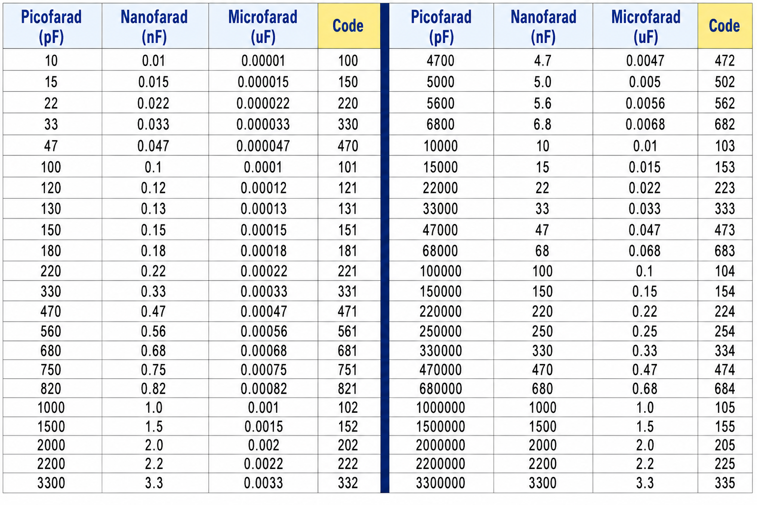
Pedal-sized resistors are almost always 1/4 watt. You can often find 1/4-watt metal film resistor kits on Amazon or eBay with a 1% tolerance (the blue resistors with five color bands), although resistor kits will not contain every value you will need. To help you learn how resistor color bands correspond to their values, go back to the Guides Page and look for the Full Color, High Resolution Resistor Chart and this handy Capacitor Code chart. I’ve linked them here for convenience, but again, take some time to look through the other guides in this section as well.
At this point, many of your questions will have already been answered, but there is much more to learn.
Capacitors come in many different sizes and materials, and some can be surprisingly large. You can learn more about them by going back to the Guides Page and reviewing the Beginners Guide to Components. This document is older and fairly extensive, but it contains a lot of valuable information. For now, you can go directly to the Capacitors section and concentrate on the information you will need for pedal building.
For example, if a capacitor in the BOM calls for a value in pF, which stands for picofarad, it will typically be one of the small orange ceramic disc capacitors. Most builds will have one or more of these. You can also identify them by looking at the PCB silkscreen, since the component outline will be a smaller box. This outline represents the part footprint and shows you the physical size and lead spacing the PCB was designed for.
Another very common type is the polyester film or box capacitor. Here, you need to pay attention not only to the capacitance value but also to the physical dimensions. The voltage rating can give you a good indication of the size; I generally look for 63V or 100V versions at most. You should also check the specifications or datasheet to make sure the capacitor has a 5mm lead spread. Most of our PCBs use a standard 5mm lead spread for film and box capacitors. You can also find convenient assorted kits containing many of the common values.
Another type you may encounter is MMLC (multilayer monolithic ceramic) capacitors. These are typically inexpensive, commonly available with a 5mm lead spread, and can often be purchased in assorted value kits. They are the yellow capacitors shown in the Beginners Pedal Building Guide. These can be used in place of polyester film or box-type capacitors as well as many of the pF (picofarad) values though you will need to pre-bend the 5mm leads to fit. When purchasing be sure they are specifically MMLC (multilayer monolithic ceramic) capacitors and never use Tantalum capacitors which are polarized and must be installed in the correct orientation.
When you see a capacitor in the BOM with a uF (microfarad) value, it will typically be an electrolytic capacitor. These are polarized, so they must be installed in the correct orientation. The capacitor itself will have polarity markings, and the PCB silkscreen will show a + next to the appropriate pad. Always pay attention to both.
You also need to consider the capacitor’s voltage rating. For these pedal builds, I typically use 25V to 63V electrolytic capacitors. Avoid using capacitors rated below 18V, since some pedal builders use 12V or 18V power supplies on circuits that can safely accommodate the higher voltage in order to gain additional headroom. Using a capacitor with too low a voltage rating can cause it to fail if the voltage across it exceeds its rating. Always check the component specifications or datasheet when you’re unsure. You can refer back to the Beginners Guide to Components for more information. You may also find assorted electrolytic capacitor kits, but these can be harder to find in the smaller sizes commonly used in pedal builds. Pay attention to the physical size and lead spacing as well. The electrolytic footprints used on our PCBs are typically 5mm or 6.3mm in diameter with 2.5mm lead spacing, depending on the component. Always check the PCB silkscreen and the component specifications before ordering to make sure the capacitor will physically fit the footprint. There are a decent amount of usable ones in this KIT but 10v are useless in pedals. 16v are fine as long as you stick with a 9v power supply.
The one exception to the uF = electrolytic rule could be a value such as 1uF. A 1uF capacitor may be an electrolytic, but it can also be a film, box, or MMLC capacitor depending on the circuit. The PCB silkscreen can help you identify which type is required: box/film capacitors generally have a rectangular footprint, while electrolytic capacitors have a circular footprint and a + marking for polarity. Always check the BOM and PCB before purchasing the part.
For the potentiometers, you will need 16mm right-angle PCB-mount potentiometers with a short solder legs. Do not use the long-leg versions.
You may also see “Trim” or “Trimmer” in the BOM. For these builds, look for 3362P Bournes trimmers. A trimmer is a small adjustable potentiometer used to set a circuit value during setup or calibration. My PCBs have an extra set of pads that will accommodate those or an RM-065 type spacing. You just drop them in which ever way they fit.
Some people prefer to avoid sourcing individual components altogether and simply pay more for a complete kit. It really depends on the person and how you prefer to approach your builds. While the assorted resistor and capacitor kits I suggested can cover many of the common parts you will need, they will not contain every resistor and capacitor value required for every build, so you will still need to source some values separately. You will also need to source parts such as trimmers, transistors, IC chips, switches, potentiometers, enclosures, and other components not included in the assortment kits. For those parts, there are several DIY pedal suppliers such as Small Bear, Stompboxparts, Lovemyswitches, and Amplified Parts where you can find what you need.
I do not sell kits myself but Small Bear and PedalPartsandKits do in the USA for which I supply them with the PCBs for.
Now that we have covered resistors, capacitors, and the Must Read Build Guides on the Guides Page, that leaves Q for transistors and D for diodes, both of which will have a specific part number or value listed in the BOM. For this build, you will also need two 3PDT footswitches and one ON/ON toggle switch, preferably with a short bat.
I would not proceed with the build until you are comfortable with this basic information and have ordered and verified the correct parts. Before soldering, physically compare your components with the PCB to make sure they are the correct size and match the silkscreen footprints.
You do not need a PCB holder to solder, but if you are working without one, it is especially helpful to install the components from shortest to tallest. Start with the resistors, followed by the 1N5817 diode, small pF ceramic capacitors, IC sockets or ICs, film/box capacitors, and finally the electrolytic capacitors. This makes things easier when you turn the PCB over for soldering.
Take your time and make sure each component is seated neatly against the PCB before soldering. Avoid excessive heat on the pads, and don’t rush the soldering process. Personally, I also use a small amount of flux when soldering switches and off-board components, as it helps produce clean, reliable solder joints.
As mentioned at the beginning it may be helpful is seeing an actual completed build from the Show Off Your Build section. Here is one Zoso Tone build and here is alternate Zoso Tone build that you can use as a visual reference. Looking at other people’s completed builds can help you understand how the components should look once installed and how everything fits together. This is in no way a substitute for reading the Guides I have recommended above, but it can be a very useful reference once you understand the basics.
And finally, don’t be afraid to ask questions here. This is my forum, not Twitter or Facebook. You are not going to get flamed for being a beginner or for asking questions. We were all beginners at some point, and I’d much rather have you ask a question than damage your PCB because you were afraid to ask. The only thing that I personally ask is that you do some reading first and then ask when you still aren’t sure, that’s what the forum is here for.
September 3, 2026 at 10:57 pm #40462kenjancefParticipantThat’s a lot of info!! I skimmed through it just now, but wanted to reply to say that I saw it. I read and downloaded the beginner pedal guide. After all of the components my biggest question is what side of the PCB is the top and/or bottom. I don’t have the boards in front of me, but I think I can figure that out from the Guide.
I truly appreciate the info, and I hope I can start on this soon!
September 4, 2026 at 3:06 am #40463BarryKeymaster“After all of the components my biggest question is what side of the PCB is the top and/or bottom.”
I answered that in the first paragraph of my previous reply and covered several other very important details you’re going to need to know before starting.
The photos in the Beginners Pedal Building Guide, along with the accompanying text on Page 2 + 3, show which side the components are inserted from and which side you solder (with all the leads sticking out).
The red text indicates hyperlinks that need to be viewed, if that wasn’t apparent. There are several of them in my previous answer, and they provide additional information that fully explains what you need to know.
I put quite a bit of time into writing my previous reply, so I’d really encourage you to go through it thoroughly before starting the build and view all of the hyperlinks. For example, the two builder-submitted Zoso Tone builds, each with build photos, the Resistor Chart, Capacitor Code Chart, Beginners Guide to Components, and more are all included in my previous reply with direct links. Going through this information first will answer most of the basic questions that will come up along the way and, most importantly, help prevent many of the common mistakes.
We cannot guarantee anyone a successful build, as that ultimately comes down to the builder, but I have given you what you need to put the odds of success in your favor.
September 4, 2026 at 3:14 pm #40466kenjancefParticipantI’m hoping I wasn’t mean about what I said. I know you put in a lot of time and effort into that post, which I greatly appreciate. All I wanted to do was let you know that I saw it and will read it in detail when I have time this weekend, that’s all…
I have Tayda doing the box for it, and I got in touch with Small Bear Electronics and just ordered their kit without the box. They happen to be local to me, so I’m hoping to get it delivered next week.
September 4, 2026 at 3:24 pm #40467BarryKeymasterThat is a very good idea to get your feet wet.
That said, take your time and digest everything while you wait. Study text and build photos etc..
-
AuthorPosts


- You must be logged in to reply to this topic.