@brd
Forum Replies Created
-
AuthorPosts
-
July 31, 2026 at 5:58 pm #39551
 brdModerator
I’m not an expert, but I would always suggest starting at the beginning. In this case it is the power supply jack, assuming the wiring is correct, you want to check continuity between the posts, however, because a short anywhere in the circuit would show continuity between the + and – posts you’ll need to disconnect the ground wire from the jack, then with the power disconnected, check continuity between positive and negative posts. if you you have continuity there then the jack is shorted. Next I suggest a voltage drop test. basically you use your DVOM set to DC voltage and place the probes on either side of each wire and component along the power supply of the circuit. If at any point you get a voltage reading close to 9V, that component or wire or trace between your probes has a short. To do this you will need to reattach the wire you disconnected from the PS jack and attach a power source. Use a battery so you don’t risk damaging a power supply. and try to be quick. First measure voltage from the power jack + to the Anode side of D1. it should be a very small reading maybe 100mV. That would show no voltage was lost across that wire. Next do the same for D1, move the red probe to the Anode side and place the black probe on the cathode side. This will be a slightly larger voltage drop because it’s a diode. Then move the red probe to cathode side of D1 and the black probe to C11 (check both sides), then check the trace between C11 and C7, and continue to both sides of C7, etc… (follow the schematic). After the charge pump test any wires, traces, and components that connect -VA to ground. remember at any point you get near 9V you found your short.
I hope that helps
July 18, 2026 at 9:51 pm #39472brdModeratorLet’s try some voltage measurements while you work on replacing the ribbon cable for the reverb switch. You don’t need the IC’s installed yet. With power supplied to the jack. Meter set to DC voltage, ground lead on a known good ground, preferably on a GND pad or jack.
First check is at the DC pad. expect a little over 9v. We don’t want to see -9V.
next check the voltage after D5. that would be on the cathode side or the stripe. Voltage should be slightly lower. This is your VC voltage as labeled in the schematic. No voltage means D5 died saving your project. stop here and replace it.
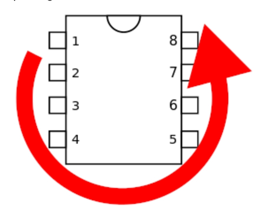
Now check IC1,IC3 IC4, and IC6 (the 8 pin IC’s) you want to check pin 8 which will be to the right of the index notch. You should have the same voltage as VC
Let us know what you find.
July 18, 2026 at 11:38 am #39462brdModeratorDon’t give up on it. You put a lot of work into that build. When the power jack wiring is confirmed, be sure you have voltage through D5 then try each section of the build with a guitar. If one or more of the effects still isn’t working report back. If your LED’s work it’s a good sign.
An audio probe is still highly recommended.
I’m not Barry, but I did stay at a Holiday Inn Express last night (bad American humor)
July 18, 2026 at 9:19 am #39460brdModeratorSorry, I couldn’t edit my previous post. I want to add that, if the power jack wiring was not the problem, an audio probe might be the best next step.
July 18, 2026 at 8:31 am #39459brdModeratorIf you look at the schematic for the Reverb in the build doc, the center lug for the Darken pot goes to ground. Your observation just confirms that is as expected.
The previous picture of the power jack and wiring looked like you had the DC (white) and ground (red) on the wrong posts of the jack. Did you fix that? The large terminal is for the ground. (unless you are using a non standard power supply)
Problems if power jack wired backwards:
D5 is your reverse polarity protection, it should hold up to 9V reversed (briefly) but damage is possible. you should avoid bypassing that or subjecting it to prolonged reverse current. It could fail as an open or short.
Other circuit damage could occur if that diode fails or reverse current is applied to the rest of the circuit. i.e. LED damage.
I hope that helps
July 16, 2026 at 5:40 pm #39454brdModeratorWire color doesn’t matter, but I noticed it looks like you have a white wire going to the ground of one jack and a black wire going to the ground of the other. Can’t see where they go under the board. Maybe a shot of the other side of the board might help too.
June 25, 2026 at 1:15 pm #39377brdModeratorI suggest a B pot
June 15, 2026 at 5:27 am #39273brdModeratorI’m glad you mentioned the switch, you’ll want to use an on-off-on switch, that will give you a third option of no clipping in the middle position.
You will need an enclosure for the PD to keep it insulated. You don’t want it shorting to the enclosure (or anything). no worries about heat.
The blue and purple wire would be interchangeable for your application.
It does not matter which row you use as long as the leads for each diode are on opposite sides of the line printed on the board
since there are two identical diodes, it doesn’t matter which goes on any row. Use the flat spot on the rim of the LED’s to be sure they are set in opposite polarity. <span style=”text-decoration: underline;”>teaching moment</span> – For D7 and D8, each diode clips half of the AC signal, when both halves are clipped with the same diodes (and number of diodes) the signal is clipped equally or symmetrically. The PD apparently clips symmetrically on it’s own, that’s why you don’t need 2 of them.
connect the blue and purple wires to a round and square pad for either D7 or D8. The other diode pads on the BE board will be empty. Since those diodes are in parallel, using a jumper would create a path of no resistance to ground and you would lose all signal.
You can measure the Vf of your PD using a meter that has a diode check option with the diode out of the circuit. The meter will supply a small current to the diode and give you a Vf reading, That is what Waylon is demonstrating at 1:12 in the video. Any difference in Vf won’t matter unless you switch while you are playing.
I hope that helps
June 13, 2026 at 6:57 pm #39267brdModeratorThat video has been popping up in my feed for a few days, I’ve been ignoring it because I’ve tried Watlon’s $5 Dumble and it sounded like *ss. I watched through it thinking it was some April fools day joke, but a quick search showed it is actually possible. As fate would have it my wife is a hobby gemologist and she had a chunk of pyrite. So I ran out to the shop and grabbed my Fluke and some wire and sure enough it seems to work. I got readings up to 1V. the whisker placement matters and I didn’t hear Walton mention what Vf he used or how he kept it stationary (maybe wax). You will want to switch the leads to be sure it gives the same reading in both directions for symmetrical clipping (or not).
Also keep in mind what I mentioned about the effect of Vf. The stock LED’s have a high Vf, going lower can drastically cut your volume. He also used a switch to change the input cap (C1) and a pot to vary the amount of signal getting to the pyrite diode (PD).
So back to your question, D7 and D8 are where you want to put a switch for your PD. I would suggest using one of Barry’s DPDT boards and putting the LED’s on one side of the switch and run wires to your PD from the other. then connect the signal wires to either of the empty diode pads on the BE board, either D7 or D8.
I don’t think my wife will give up her Pyrite so there isn’t much chance I’ll get to try this unless she finds another one. Please let us know how it works for you.
Best
June 12, 2026 at 8:57 am #39260brdModeratorIf you can tell us what you are trying to achieve it would be easier to give you some guidance.
As I mentioned, the forward voltage is what effects the signal. An average red LED has a forward voltage around 1.6 to 2.0 volts so any signal above the 1.6 to 2.0 volts will be clipped. The 1N4148 diodes called for D3-D6 have a Vf around 1V. They will clip more and therefore compress more and lower the signal volume. However putting 2 of them in series is additive for the Vf, so 2 of them in series will give you around 2V Vf.
If I haven’t made this complicated enough, the type of diode affects the clipping in how fast or slow the clipping turns on and off. This is why germanium diodes are said to have softer clipping. Diodes in an IC feedback loop have softer clipping because of the characteristics of the IC used.
The final twist when using multiple clipping stages is to consider placement . Using LED’s after a clipping stage with a low Vf will not do much unless the signal is amplified between them.
So simply put if you want more clipping and a more compressed sound lower the Vf, if you want less clipping and a louder more open sound raise the Vf or even eliminate the diodes.
There is still more to this magic and hopefully someone smarter than me will correct anything I got wrong, but I hope that helps
June 10, 2026 at 8:26 pm #39248brdModeratorI was about to modify my post to add some clarification, when I realized I contradicted Barry. I don’t like the terms hard and soft clipping, they are ambiguous. Germanium diodes give what some people call soft clipping too. Using a diode with a low Vf gives more or harder clipping than a diode with a higher Vf. D3 – D6 add the most clipping in this circuit, so Barry is not wrong by that definition, it just matters what you are trying to achieve.
No clipping is another popular mod and likely the easiest to do with just a switch.
Sorry for any confusion, I am not one of the Gurus here.
June 10, 2026 at 7:22 pm #39246brdModeratorD7 and D8 are connected from the signal path to ground (or VB) they provide what is referred to as hard clipping. the other 2 sets of clipping diodes (D1, D2) and (D3,D4,D5,D6) are contained in the feedback loop of 2 IC’s. They create what is commonly referred to as soft clipping.
D3, D4, D5, D6 are not in series they are two sets of 2 diodes in series, placed in parallel of each other with opposite polarity. giving symmetrical clipping.
I’m a big fan of Mosfet clipping like used in a zen drive or Barry’s Zenith or NT Dumble tone. The old ODC circuit uses Mosfets for hard clipping.
Socket and see as they say.
Hope that helps
May 12, 2026 at 7:19 am #39099brdModeratorVery well done. It looks better than my last build. After the space modulator you’ll be ready to start building tube amps. I just recently discovered the magic of Barry’s Emerald Ring into a fuzz face, very funky. My next advice is to make an audio probe https://drive.google.com/file/d/1T9OsJ0riQhm1QFWPfNQ5q5guikuFKDRN/view. Hopefully you will never need it, but it’s a must have for troubleshooting.
Best
BRD
April 27, 2026 at 9:59 pm #38969brdModeratortip #4 use sockets for all IC’s and transistors.
I don’t know of any way to test the IC’s until it’s finished.
I think I would wait and see There is a chance they have been damaged by the heat already, but de-soldering them will just increase that chance plus you risk damaging the pads on the board. The only difficult point I can see is the pads for the large IC will be under the Volume pot when it’s finished. On the other hand if you already have replacements it could be easier to do it now. Tough call.
Maybe wait for another opinion.
April 26, 2026 at 6:42 am #38960brdModeratorVokinn72
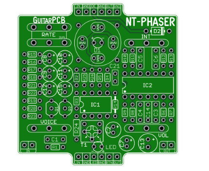
Welcome to the exciting journey that is pedal building. I’m not one of the gurus here but I try to help where I can. As for your question about the diodes. the build doc has a picture of the board that I’m using for reference. there are only 2 diodes in the build. D1 is an LED, D2 is a 1N5817. The printing on the board sometimes has a circle with a flat spot to help orientate an LED, this one just has a plus and minus sign. here is a picture to help you.
The LED has a flat spot. The positive side is the Anode, the negative side is the Cathode.D2 should be installed as shown in the build doc in the upper right corner. The cathode should be to the right.
As far as tips to get started.
- First read the beginners guides Barry mentioned.
- Read the build doc. There are usually build notes for important information.
- get good at soldering. Use a small pointed tip, and get the temp right so you can get a good solder as quickly as possible. With my rig 7 seconds is about all it takes.3 second to warm up 1 second to melt the solder and 3 second to be sure it flows around the pad. Barry’s boards are pretty robust but you can still damage any board by getting the pad too hot.
Other tips
- start with the components that lay the closest to the board and work your way up. resistors first, then diodes. then usually sockets and small MLCC caps then the box caps and electrolytic’s last. I use a small piece of electrical tape sometimes to hold components in place.
- Get good at de-soldering. I don’t like using the braids. I use a pump that looks like a large pen that has a plunger and a button to trigger the suction.
- take your time soldering switches and pots, give a good 30 seconds at least, between soldering the leads to avoid overheating the guts.
I hope that helps
April 25, 2026 at 7:37 pm #38955brdModeratorIf you are looking to modify the mid scoop, my suggestion for the least extra components is to use the following values in the tone stack
C10 3n3
C11 10n
R18 39K
R20 39K
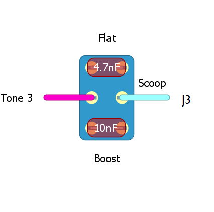
Then you can use a DPDT on-off-on switch with 2 caps as shown below to get a mid scoop, flat response or mid boost.
This is borrowed from tagboardeffects for a Hizumitas work alike
You can plug the values into the BMP tone stack calculator on TSC in the web to see the effects. The caps will parallel C10 so you will have effective values of 3.3nf, 8nf and 13.3nf for C10
I hope that helps
February 11, 2026 at 6:04 am #38320brdModeratorHere is a pinout for a metal can type 2N2222. The leg closest to the tag should go to the E pad on the board if using this type.
It’s handy to have a component tester to identify component leads. ( I use an Atlas DCA55 ) it can save time instead of searching for datasheets. Hope that helps.
-
AuthorPosts
 The LED has a flat spot. The positive side is the Anode, the negative side is the Cathode.