@barry
Forum Replies Created
-
AuthorPosts
-
 BarryKeymaster
The yellow and green wires from the foot switch are connected to the wrong lugs of the jacks. As Mark said, reverse them.
I strongly suggest reviewing the entire guides page before proceeding. You can access that by clicking the link in the main menu bar up top.
There are several beginner guides that would be very helpful to you. I agree with Mark in that I would not expect your build to work or at best intermittently if you have not soldered the wiring connections. All connection throughout the circuit need to be soldered. Also trim leads So they don’t short on something and act as noise antennae.
BarryKeymasterRemember to use the “Image Icon” to upload only one image at a time.
I am testing it right now below:
As shown above posting a photo is working fine.
————————————————————
Back to your build: In addition to the pictures we also need:
- Does the circuit pass guitar signal in both bypass and active modes?
- Be sure your PT2399 is properly seated (all 16 pins).
- Test an alternate PT2399 chip if you have one.
- Give us Voltage readings for IC1, IC2 & IC3 (see the Crash Course Guide – Page 8 if needed)
BarryKeymasterSo any thoughts or comments on this wonderful build?
The image is a link to the build story btw.
BarryKeymasterI am not sure where the broken link is.
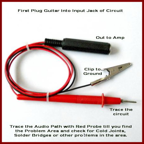
I grabbed this from the Guides Page which has the info you will need:
The Audio Probe Explained – courtesy of Tonmann, Billy, Wilkie and Bruce
Continuity should be present from the battery supply to the current limiting resistor. That would not explain “no sound” and only affect the functioning of the LED. I am curious if you eventually populated R12 with at least a Jumper as I mentioned in my 1st reply since that would cause “no sound”.
If you have some photos of your build that are current it would be worth us having a look.
BarryKeymasterThe Non-T pads are grounds which you may use “conveniently” to wire to the sleeves. Just like in the guides I posted above.
You can also check the continuity of the entire circuit using your DMM. Here is the Crash Course Guide Link taken from the Guides Page. Check page 9. The Crash Course Guide .
As long as there is a common ground however it does not matter which ground you use as different strokes for different folks. How about some updated photos showing the finished build so we help you can examine it.
BarryKeymasterI have not experienced that difference from Muffs made since the 90’s but that is about it. The oldest one I have is a Russian. You could easily make your Muff’n louder. Perhaps the answer to your question though is here?
BarryKeymasterHi Rick and welcome!
Your build looks very nice. I am going to blow through these questions really quick because I am doing a lot of running today. If I miss something or someone wants to embellish please do.
Okay:
- Yes. BO is Board Out and BI is Board In.
- Yes. It is a six and one/half dozen kind of deal or ham and mustard vs. mustard and ham.
- Yes. If you flip it the other color will be the On color. You can test this easily with a 3 to 5v coin battery.
- Yes on the Pots. It is another six and one/half deal since many would wire pots through the top and fold the pots over when installing to the enclosure. No rights or wrongs. This is one of our first from over 10 years ago and we were still figuring out our standards.
- You can socket that area if you like. It will not work without that resistor in the circuit. The standard value we have I feel is a good value for most guitars until you enter high output territory. Over 10k.
I hope that helps. Sorry for being in a rush but I think I covered everything.
Here is the link to our Guides Page if you have other questions on this or future builds.
Here for convenience below are two charts take from the Guides Page.
BarryKeymasterStill need voltages.
You can only upload 1 pic at a time.
You cannot link pics without it being an absolute direct link. In other words most photo hosts do not provide direct links for commercial reasons. If you are using a VPN while in the forum not much will work. My site is setup to block all VPN to prevent brute force hammering my site for passwords.
Here is a direct link from my site:
Here is an uploaded picture.
BarryKeymasterAgain if you are willing to drill your own (which is not that bad) I point to Small Bear who have at least 9 unique colorsas well as black and white. Here is the info:
“Many of us seem to be overlooking Small Bear who are an awesome DIY Pedal Parts provider from NY and have just about everything and they are very much worth supporting.”
Here is a direct link to enclosures: LINK
As for boards that are out of stock if you purchase at least 10 of the regular size boards or 25 of the smaller mod boards I can include them in my next order. Use the Contact Me form to inquire. I can also offer a slight discount for multi-board ordering.
BarryKeymasterYes we lovingly refer to this as a Kenny.
This allows you to make a choice between a set of pads to use either an LED or alternate diode such as Silicon, Germanium etc.. while maintaining a clear image of the Cathode regardless of choice and without using up precious board real estate especially in the case where one preference is usually encouraged.
BarryKeymasterAs far as posting pics here is a test:
It is working I would try again.
BarryKeymasterThat is something Bruce will need to address.
I left him a message.
I am certain he will take care of it for you.
BarryKeymasterVery Nice!
I am glad you finished it up.
BarryKeymasterVery Nice!
Glad to see our Easy Order Switching boards being put to good use.
I remember hand etching all of those boards too well.
BarryKeymasterLooking at your Photo Q1 and Q2 are backwards from the board silkscreen. That would cause the issue you speak of.
I just noticed you made a substitute. BS170 may have different characteristics. Double check each Datasheet.
BarryKeymasterYes D5 the Status LED and R9 the Status LED CLR should not be installed since they are installed on the 3PDT switch now but if they are it wouldn’t matter. With no D8 that is not an issue.
I will fix the typo.
BarryKeymasterMany of us seem to be overlooking Small Bear who are an awesome DIY Pedal Parts provider from NY and have just about everything and they are very much worth supporting.
Here is another direct link to enclosures: LINK
-
AuthorPosts