Your Source for DIY Pedal PCBs and NostalgiTone! › GuitarPCB Forum › General DIY Pedal Discussion › Capt. Munch Initial Test
- This topic has 28 replies, 4 voices, and was last updated 6 years, 5 months ago by
 Barry.
-
AuthorPosts
-
December 19, 2019 at 12:00 pm #8814AnonymousInactive
Hello GuitarPCBers:
I have assembled and wired the Capt. Munch kit components and I am ready to begin an initial test. See photo inserted below.
Thanks in advance for your help and all the great work on GuitarPCB.
I was unable to resolve a few issues during assembly. Could you please answer the following questions before I proceed with testing?
- Was I correct to wire 3PDT B0 and B1 to the Capt Munch board In and Out “T” pads, or should they have been wired to the unlabeled In and Out pads?
- Was I correct to wire all three SW1 pads from the Capt Munch board to the SPDT switch?
- Was I correct to wire the longest cathode leg of the common anode LED to pad 1 of 3PDT D1?
- Was I correct to wire pad 1 to lug 1, pad 2 to lug 2 and pad 3 to lug 3 for each of the the potentiometers? Doing so required crossing wires for each. This is not shown below because it is under the Capt Munch board.
- Was I correct to leave R12 unpopulated until I determine that it is required?
Thanks, Rick
December 19, 2019 at 1:15 pm #8819BillyModeratorAll correct, R12 would intially be a jumper until you decide if the inputs to high then you would change it to a resistor between 47 to 100K i’d use sockets till you find what you like, regarding the common anode bicolour LED it doesn’t really matter which way around you solder the cathodes it’ll still work
You only have to consider it if you want a specific colour for bypass and effect on
December 19, 2019 at 1:20 pm #8820BarryKeymasterHi Rick and welcome!
Your build looks very nice. I am going to blow through these questions really quick because I am doing a lot of running today. If I miss something or someone wants to embellish please do.
Okay:
- Yes. BO is Board Out and BI is Board In.
- Yes. It is a six and one/half dozen kind of deal or ham and mustard vs. mustard and ham.
- Yes. If you flip it the other color will be the On color. You can test this easily with a 3 to 5v coin battery.
- Yes on the Pots. It is another six and one/half deal since many would wire pots through the top and fold the pots over when installing to the enclosure. No rights or wrongs. This is one of our first from over 10 years ago and we were still figuring out our standards.
- You can socket that area if you like. It will not work without that resistor in the circuit. The standard value we have I feel is a good value for most guitars until you enter high output territory. Over 10k.
I hope that helps. Sorry for being in a rush but I think I covered everything.
Here is the link to our Guides Page if you have other questions on this or future builds.
Here for convenience below are two charts take from the Guides Page.
December 28, 2019 at 9:14 am #9094AnonymousInactiveThanks to those that responded.
I noticed an inconsistency between my wiring which is based on the “Tonman Version” and the 3PDT wiring posted below. The Tonman Version wires the sleeves of the input and output jacks to left and right 3PDT ground pads of the 3PDT board, whereas the diagram posted below wires the sleeves of the input and output jacks to the respective non-T input and outputs of the main board.
Is this significant?
My current test results produce no output in effects mode, but output in bypass mode. I am ready to begin testing with my audio probe.
Thanks again in advance and Happy New Year to all !
December 28, 2019 at 11:15 am #9097BarryKeymasterThe Non-T pads are grounds which you may use “conveniently” to wire to the sleeves. Just like in the guides I posted above.
You can also check the continuity of the entire circuit using your DMM. Here is the Crash Course Guide Link taken from the Guides Page. Check page 9. The Crash Course Guide .
As long as there is a common ground however it does not matter which ground you use as different strokes for different folks. How about some updated photos showing the finished build so we help you can examine it.
December 28, 2019 at 9:17 pm #9104BillyModeratorAre you getting power to the main board , it’s hard to see but your wires on the DC jack look fairly close can’t really see if you’ve got big blobs of solder shorting those wires and also cant really see where the DC jack wires go to
I’m assuming they go to the 3PDT board +9v and ground pads and power and ground are then jumpered from there to the main pcb so I’d check that first on the main board +9v and ground pad to ensure it’s getting power
You’d get bypass signal with no power it basically means that your jacks are wired correctly to the bypassed side / throw of the 3PDT
December 29, 2019 at 7:33 pm #9112AnonymousInactiveThanks Barry. I believe that I have successfully verified continuity using the “Easy Wiring Diagram” on page 9 of the Crash Course Guide. I used the color coding in the diagram an got a beep from my DMM on each connection.
I had one question interpreting that diagram in the orange test scheme. Should I get continuity on Lug #4 of the 3PDT board? I get it on the CLR, but not Lug #4. I cannot interpret the meaning of the orange circle to the right of the CLR box in the diagram and the significance of the orange line from the circle to Lung #4.
I have an audio probe and I’m ready to start testing with the probe, but I found the “Using an Audio Probe to Debug Builds” link is broken. Could you please provide a valid link?
—
rick
December 29, 2019 at 7:51 pm #9113AnonymousInactiveThanks Billy.
I do not know how to test whether I am getting power to the main board. I am brand new at this, but if you tell me what to test I will report the results. See also the results I just reported to Barry.
There’s no evidence of a short from solder crossing the +9v and ground lugs on the mains jack. Your assumption is correct that the +9v mains jack wire connects first to the left +9v pad on the 3PDT board, then jumpers to the main board from the right +9v pad. The ground connects first to the top left ground pad, then jumpers to the main board.
Thanks again for taking the time to help. If you could tell me how to test whether there is power on the 3PDT and main boards, I will report my results.
—
rick
December 29, 2019 at 9:02 pm #9128BarryKeymasterI am not sure where the broken link is.
I grabbed this from the Guides Page which has the info you will need:
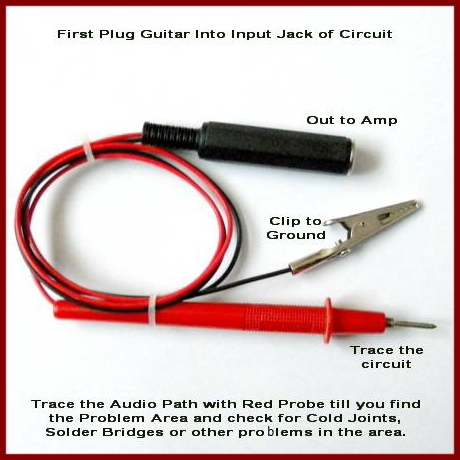
The Audio Probe Explained – courtesy of Tonmann, Billy, Wilkie and Bruce
Continuity should be present from the battery supply to the current limiting resistor. That would not explain “no sound” and only affect the functioning of the LED. I am curious if you eventually populated R12 with at least a Jumper as I mentioned in my 1st reply since that would cause “no sound”.
If you have some photos of your build that are current it would be worth us having a look.
December 30, 2019 at 5:55 am #9136BillyModeratorTo test you are getting power to the main Cap’n munch pcb set your meter to 20V DC place your black probe on the ground pad and your red probe on the +9v pad
If your LED illuminates that would mean you are getting power to the 3PDT board so doing this is just to check you are getting power to the Cap’n munch pcb via your jumpers
January 1, 2020 at 2:58 pm #9192AnonymousInactiveHappy New Year and thanks to Billy and Barry.
Billy: I have verified power on the 3PDT board because the LED illuminates red in bypass mode and green in effects mode. I also measured 9.05v with my DMM on the mains jack lugs and the 3PDT +9v and G pads. I also verified power on the main board by measuring 9.05v on the +9v and GND pads.
Barry : Yes, I did populate R12.
I also started to probe the audio path.
Just to make sure I am doing this right I will review my approach.
- I applied power to the pedal and using my audio probe I verified audio on one leg of R1 and one leg of C1.
- I unplugged the pedal and measured 0.009 MΩ of resistance on R1.
- I measured 0.535 μF on C1.
I measured the values at least three times to ensure consistency.
Please let me know if this approach is correct.
The measured values differ from those reported in the Capt. Munch build doc which are 1 MΩ and 22nF respectively.
Please advise on how to interpret the measurements.
—
rick
January 1, 2020 at 11:03 pm #9203BillyModeratorYou can’t accurately measure components in circuit whilst they are connected to other components
Much better to do a visual check of your components ensuring they are the correct value and polarity is correct
You can check resistors by colour band I use this site
https://samstechlib.com/610938/en/read/
I’ve checked the components I can see all seem to be correct value and polarity
I’ve roughly traced the audio path for you below you want to follow the red line from input to output the simplest way to check is from the IN T pad through C1 and R2 into pin 3 IC1A out pin 1 to P1 lug 2 out lug 3 to C5, R5 into pin 6 IC1B out of pin 7 to C7, R7, C8, C9, R9 into P2 lug 3 out lug 2 to IC2B pin 6 out pin 7 to C11, R12 into P3 lug 3 out lug 2 to the OUT T pad that way you’re checking all the inputs and outputs directly
Make sure you make good connections when probing you will notice differences in audio for example at the IN T pad it will be clean signal and as you go through amplification stages etc it’ll get louder
Set your volume low to save you jumping out of your skin! If you have a looper pedal record a loop and use that as your input audio to keep 2 hands free
Read the audio probe explained PDF and you should be fine
January 4, 2020 at 8:55 pm #9273AnonymousInactiveMany thanks, Billy.
I had a bad solder joint on lug 2 of P3. The pedal now produces output, but there’s not much output.
As I probed the audio path, I noticed some components produced “low output,” so I can probably identify them along the path.
Other than that how would I proceed to analyze a “low output” and how would I measure output level?
—
rick
January 5, 2020 at 1:59 pm #9283BillyModeratorDo you lose volume on all positions of the diode switch you will get a drop in volume depending on which position it’s in the middle should be the loudest
Check the solder joints on the output jack lugs make sure the solder flows nicely the solder on your tip looks like it could be dry
Where do you loose volume in the circuit
January 24, 2020 at 3:54 pm #10060AnonymousInactiveThanks Billy,
Sorry for the delay in getting back to you. I had some chores around the house that took priority.
To answer your questions :
- All positions of the diode switch are at reduced volume;
- I re-flowed the solder on the output jack lugs;
- a) Using my probe, I established the volume level at the input jack as “normal volume”; b) The In pad on the main board is normal volume; c) On C1, the “inside leg” is normal volume. By “inside leg” I mean the leg towards to middle, or inside or the board. On C1 the outside leg is about “half volume.: Half volume is subjective because I don’t know how to measure the volume. On R2, both legs are subjectively half volume. On R3 the bottom leg produces noise and the top leg produces half volume, where bottom leg is the one closest to C1.
I did not test further, hoping you could provide feedback on my testing approach. Is there any way to measure the volume, other than to subjectively say normal and half?
—
rick
January 24, 2020 at 4:40 pm #10061BarryKeymasterCan you post some clear updated photos of the whole build as well as just the board.
January 31, 2020 at 2:10 pm #10412AnonymousInactiveAttached you will find new detailed photos. This first photo shows underside of the main board.
The next photo shows the top, right-hand side of the main board.
The next photo shows the top, left-hand side of the main board.
The final photo is another view of the underside of the main board.
Feel free to let me know if you would like additional photos.
Also, there appears to be a white substance generated as a result of the audio probe testing. What is that?
I had already posted a top-down view of both boards and the jacks. Please let me know if that does not satisfy your requirement for a photo of the “whole build.”
-
AuthorPosts


- You must be logged in to reply to this topic.