@barry
Forum Replies Created
-
AuthorPosts
-
 BarryKeymaster
Sounds like you are “Ready to Rock”
BarryKeymasterHere are some additional notes:
R5: This has been added to prevent the Gain pot from being turned completely off.
This is useful in that you can set the minimum gain (via the value of R5) when the Gain pot is at 0% rotation, this will give more usage out of the gain pot itself. There are two methods to adjust the value of R5 for minimum gain:
Method 1:Socket R5 and try different values –10kΩ is suggested as a starting point.
Method 2 (The second method is a bit more involved): Don’t install R5, wire lugs 2 & 3 of the Gain pot as usual. Wire lug 1 of the Gain pot to the right hand (from the layout diagram) pad of R5: Set the Gain pot to give the desired minimum gain. Remove the wire from the right hand pad of R5 and measure the resistance between lugs 1 & 2Choose the nearest standard value for R5 and solder it to the board.
R7 –TR1: This is a version of the Ruetz mod.
I don’t think this mod really warrants an external pot so I have used an on board trim pot. If you want to make this mod with an external pot, don’t install the trim pot and wire the external pot to the respective pads. It basically reduces the high frequencies a lot less than the bass and mid frequencies when the gain pot is turned down.The best results will be obtained when the R7 –TR1 value is between 0Ω (a wire jumper) and 100Ω, there are several methods to achieve this: Socket R7 and don’t install the trim pot. Try different values for R7 ranging from a jumper up to 100Ω. This is an unsatisfactory method as many people won’t have (enough) low-value resistors in their parts bin. Install the trim pot and don’t install R7, set the trim pot to taste. Using a 1kΩ trim pot (which is more obtainable) in conjunction with R7 at 120Ω or 100Ω will yield the desired results
BarryKeymasterThis was an original Tonmann design from Germany and unfortunately he is not around to answer details but this board has been in circulation for 11 years and many people swear by our values. One thing I can say at a glance is that some of the original values are obviously higher than need to be for a guitar pedal coupled with the fact that we do not like using electrolytics in the audio path which would explain most of it.
As Wilkie said you can put original values in and use MMLC capacitors which have a 5mm lead spread.
Here is a chart that shows the changes.
BarryKeymasterThanks for that info Billy.
If it helps in regard to the newer v4 Swah board there is a thread of a successful build here:
While the picture is hard to see you can tell it is a v4 board by the dual 9v & Ground pads in the top right corner which is only on v4.
BarryKeymasterWelcome Steve,
The switch adds or subtracts D5 and D6 respectively into the circuit making the clipping diodes asymmetrical or not. There is more info on clipping diodes on our Guides Page under A Beginners Guide to Components pages 10-13 if needed. Simply put it makes a clipping tonal difference to what I believe to be a set and forget option.
Here is an image from the Schematic in the Build Doc. I have updated the Build Doc notes.
BarryKeymasterYou need to go over your entire build and make sure all grounding is good.
Re-flow.
Please post clear pictures and we can advise.
BarryKeymasterThat is your ground so that would cause it. Fortunately our boards contain extra ground pads so find a way to get common ground.
BarryKeymasterI stared at this for a while and I think you got it!
I really was making sure you had common ground completely covered.
While that will work you can save some wire length and extra tangle by removing 3 ground wires each marked with a pair of blue lines.
Then add the 2 ground wires indicated by my blue arrows. See if that makes sense.
Good luck.
BarryKeymasterI would re-flow this joint first.
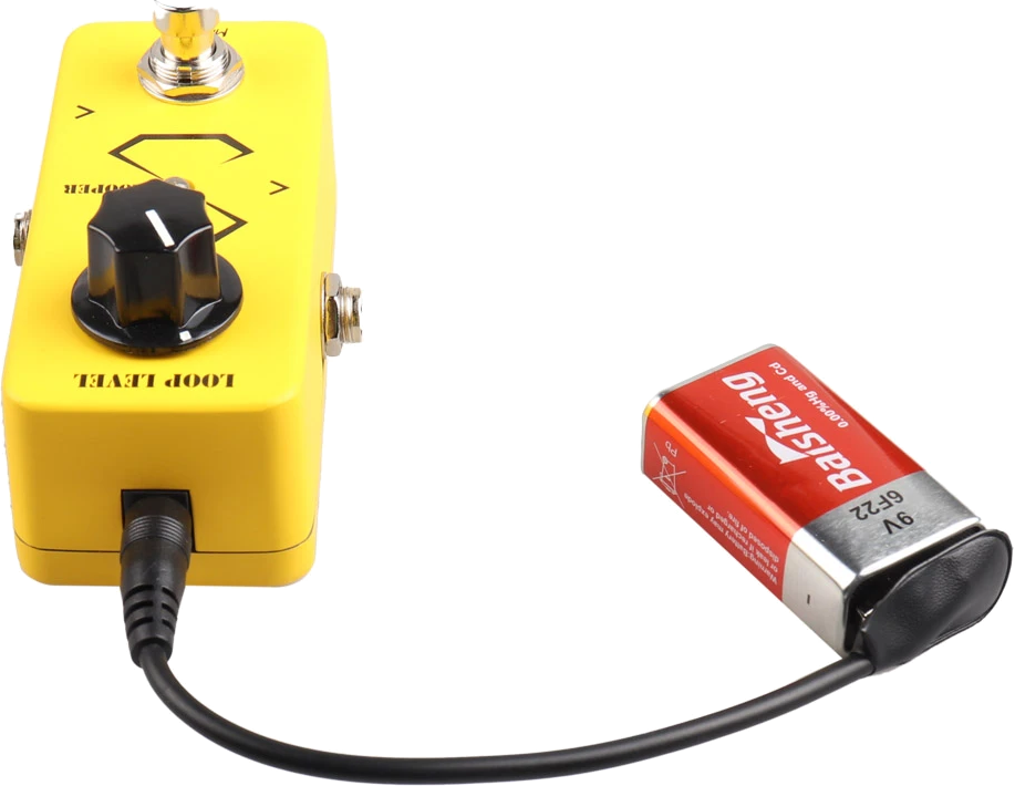
If you are satisfied that your build has then got 100% good solder joints a battery test would be a great way to rule out many potential issues such as this handy tool below since a battery will not produce any noise of its own:
Finally this will work on its own however it is meant to be used with some kind of Fuzz or Distortion which will help bring out the Hendrix style octaves which are more prominent using the neck pickup around the 5th to 12th fret. My demo shows the kind of Octave tones you should expect from this circuit. Also perfectly matched capacitors are very important as well.
If all of the that fails then tell us what transistors you are using and give us voltages on the 3 transistors.
BarryKeymasterVery nice and thanks for sharing!
BarryKeymasterThe fact the v4 board tested fine is all I can tell you undeniably from my shop.
As for my other advice I am not saying that you exactly lifted pads with heat, only that is a common that happens.
The Soldapullt is a recommendation because I love it. $25 or less most shops.
The other thread you refer to having the same exact issue had very different voltage readings so the cause is not the same.
His are in black vs. yours in violet.
Q1: 6.93, 4.17, 3.2 – Q1: 0.03, 0.03, 0.59
Q2: 4.98, 4.02, 3.58 – Q2: 4.95, 1.03, 1.13
Q3: 4.98, 3.94, 3.33 – Q3: 4.95, 1.13, 1.30
TL074: Pin 14: 4.35 – 1.6
I only listed the obvious ones that would make a difference for brevity.
The reason for pointing out the voltage readings here is so that people reading in the future won’t try to lump them together. Just so we are clear I am not trying to point at anything other than the difference.
Forums are great for troubleshooting and we love to help but unfortunately most people do not bother to show off their successful builds and even worse can disappear forever when they fix a troubleshoot and don’t bother to let us know the results.
Again anything is possible certainly and this is simply the best info I can give from my end.
I would start by confirming the ground plane with a fresh board. I do like good lager and will drink one with you when you are done. I like them especially with a nice Corta Panda on the side.
BarryKeymasterIf it helps I just checked the continuity of every pad across the board which is from the same lot as yours.
The only pads connecting with ground are the ones that are supposed to and none of the ones you mentioned are connected.
These boards are all fully checked from the factory as well as they probe every board for potential issues.
I would mention that I mod my boards a lot trying out new ideas, values and potential mods and the two things that keep me from lifting a pad is resisting the temptation of using too much heat in tandem with repeated applications of the conical tip to the pad while trying to work a lead out and I use a Soldapullt III PT-409 desoldering pump which will remove all or most solder in a single try. It is so much better than all of the knock-offs.
BarryKeymasterThanks for sharing, very nice!
BarryKeymasterDid you try it with 2 good short cables (10ft or less) with only a guitar and no other pedals plugged in?
That way you can rule out several common issues right away. Remember we sold thousands of these worldwide over 10 years so there is no real good reason why one circuit would be different than the rest. The other thing I would do is a solid re-flow as part of a standard troubleshoot.
Other than that start a new thread with photos and voltages so we can have a look and we will be happy to try and help.
BarryKeymasterYou should look at Wilkies Wah Guide on the Guides Page before moving on and try a few mods.
BarryKeymasterBeat me by 1 minute at 2AM here Billy. Not sure what that says.
BarryKeymasterTypically a problem like this is in the off-board wiring.
I am having trouble seeing clearly or trying to make sense of the 3PDT wiring scheme and see what is going to where in regards to the audio path.
If someone else can open their eyeballs any further pleas jump in.
-
AuthorPosts