@barry
Forum Replies Created
-
AuthorPosts
-
 BarryKeymaster
Q: For normal usage, install D1-D4. There will be NO SW1 …
SW1 allows you to switch between the clipping options that are On-board. Only when using A/B pads for off-board modding you do you not need SW1 since you are already going to be switching using a switch which is Off-board.
Even if you do not have any experience reading a schematic you should always practice looking at them since in this case you will see D1 through D4 and you will see the switch symbol showing how it switches. It can become quite intuitive very quickly. In the image below it shows you that there are two sides to the switch SW1a & SW1b (see components guide) so the schematic shows you are switching between D1 through D4 on SW1a and D5 & D6 and SW1b for your two different on-board clipping options.
By the way be sure to check out all of the Guides on the Guides Page. Anything in Orange is a link.
I hope that helps.
BarryKeymasterTo learn more about diodes used as clipping options check out our supplemental guides on the Guides Page particularly Page 13 & 14 of the Beginners Guide to components.
The Guides Page can be found by using the large red button either on the Home Page or the Forum Home Page. The main build docs assume the basics and some understanding of schematics. Our supplemental guides are available for anything you wish to learn more about.
BarryKeymasterIn about a week.
BarryKeymasterNow that I finally found time for a detailed answer…
I figure I would cover all the bases for others reading as well.
The Combo Guide contains information on using the WIRE method in detail which is what most of us use as a DIY community especially for combos. Have a look at the 100’s of customer builds for ideas in our Slideshow Section located in the Main Menu Bar. Other options include using Pot Condoms in case you have bare metal pots to set the boards on (yes you can indeed use double side tape to secure the boards to the pots).
Many of our boards (including the Mini-Me) can be fitted with 16mm Right Angle board mounted pots eliminating any issue or need for another type of solution (except in your rack situation) since the Pots will hold the board in place.
Even the ones with smaller pads (including the Bass OD) will accommodate 9mm on-board Pots as well. That said hand wiring allows for many boards to fit into a single enclosure. You can find out more about the 9mm Pot solution in our GuitarPCB Tips section on the Guides Page.
Since it is rack mount I think 3M double sided tape which is non-conductive would work and…
I also sell PCB Secure Mounts in the SHOP for yet another option. It has pictures and examples. This is how we cover most bases while providing the smallest size boards to fit into the two most popular enclosure sizes.
Every Colored Text above is a direct link. I hope that helps.
BarryKeymasterSee the combo build guide on the Guides Page for ideas.
If you missed it use the big red button below the Forum home page or also on our main home page.
Many of us use the method MXR used for 20 years meaning the Wiring holds the boards into place. There are other alternatives such as our pcb secure mounts etc…
BarryKeymasterWe would need a schematic, several very clear gutshots and complete specifics of the Wiring code used throughout the pedal before suggesting a potential Wiring Guide.
True Blending would be much more complex as you would need to wire it in parallel with the original circuit and determine the Phase of the original circuit. A series off/on Wiring would be easier by comparison.
An easier, actual Muff circuit would be the Opamp version we call the BMPOA. If you are just looking for a simple Fuzz with one control then as Matt suggested try the One Knob Fuzz.
Before committing to the original plan you might just want to try building your own combo pedal from start to finish especially if you are a total noob as you say. There is a combo guide located on the Guides Page and plenty of excellent circuits to choose from, the Wiring of each circuit is known, schematics are available and a much higher chance of success without a “troubleshoot” scenario.
BarryKeymasterYes, it is just a matter of time.
Any board not listed in the Shop is temporarily unavailable till I am able to restock it.
If anyone needs a build doc however they are available as part of a Master List on the Guides page.
BarryKeymasterA faulty switch which can happen from overheating a lug is possible, a cold solder joint etc. If the LED works outside of the connection (ruling out a faulty LED) then it should work with the connection unless something is breaking that connection. That will be hard for us to discover through photos. I would start by testing continuity with the switch in both positions.
BarryKeymasterThe very top orange link on the Guides Page contains the master list of all build docs “alphabetized” including the one you need.
BarryKeymasterAll Build Docs are located on the Guides Page in Alphabetical Order.
BarryKeymasterThe change was purely cosmetic.
As Billy pointed out we do not recommend the Max1044 chip.
From the build doc: The charge pump you use must be compatible with the 7660/1044 pin layout. Some charge pumps have a frequency-boost feature which will increase the oscillator from the default 10kHz up to 35-45kHz. We recommend that you use a charge pump with this boost feature to avoid any whine or clock noise. We have seen a high failure rate with some manufacturers’ MAX1044 chips, so we prefer the 7660S (e.g.: TC7660SCPA).
What is your current bias voltage set at for the collector of Q3?
BarryKeymasterPlease check the Guides Page:
Your 3PDT Pad numbering (shown above) is opposite what it should be. Again refer to the Guide.
That said I think you may be using the wrong LED type. We require Common Anode and not Common Cathode. It is an easy coin battery test “see image below” Only use battery under 4v.
Here is the wiring and especially the 3PDT Lug Numbering from the Guides Page
Here is the Continuity Test from the Guides Page:
BarryKeymasterIs this doc. Still posted somewhere?
BarryKeymasterI always source from Small Bear, PedalPartsPlus, Mouser (search filters makes it easy) and eBay (carefully).
BarryKeymasterPlease follow this UNIVERSAL diagram which can be found on the Guides Page:
From your picture library you have the Yellow wire going to the Mono Jack connected to the (Sleeve) or ground instead of the Audio Tip lug. Reverse them.
As for sharing of “common grounds” there are many ways to do that which is why we have extra pads on the boards to suit any builders style. It will all work as long as ground is found to be shared from power to main board to wiring board and Jacks.
BarryKeymasterTest your pedal only with a battery to rule out a ton of issues not pedal related.
Batteries cannot produce noise thus eliminating all power supply related issues.
Only test the pedal by itself to rule out several other issues.
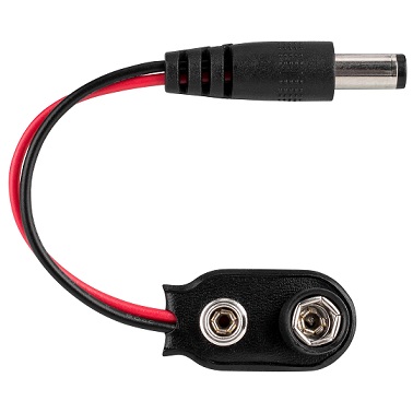
You can connect a battery to your pedal using your 2.1mm connector attached to a battery strap but be sure it is wired correctly so that it is Negative Tip.
This is an excellent tool to always have handy when troubleshooting.
BarryKeymasterBlack ground wires appear to be connected to the side of Tip Jack?
It should be like this:
-
AuthorPosts