
Your Source for DIY Pedal PCBs and NostalgiTone! › GuitarPCB Forum › General DIY Pedal Discussion › Diagnosing A PCB Power Problem – Probable Short
- This topic has 3 replies, 2 voices, and was last updated 2 months, 1 week ago by
 brd.
brd.

-
AuthorPosts
-
July 30, 2026 at 4:58 pm #39542Big OParticipant
It has been awhile since I have posted anything of substance on this board, but I am asking for some assistance on a pedal I built awhile ago, if someone would be so kind to provide some input.
The other day I picked up one of my pedals that I haven’t played in awhile. I plugged the power supply cable into the DC power jack and the pedal wouldn’t turn on after depressing the footswitch. True bypass works fine. The last time I used the pedal it worked fine, but it has been a few months.
I got out my DMM and checked the voltage coming from the power input jack and it registered only about 0.7V, and then measuring on the PCB board at the power input, I got only approximately 0.4V. Checking the isolated power supply I was using showed that approximately 9.6V was coming from the barrel tip, so the problem was not the power supply.
I then placed a 9V battery (output measured 9.3V) into the battery clip and still got unusual low voltage readings. I also noticed the battery getting very warm and I immediately deduced that there may be a short somewhere in the circuit. This was confirmed when I discovered that the LED on the power supply at the cable origin turned off as soon as I connected the other end to the pedal – this is supposed to be a failsafe of the power supply that indicated a short somewhere in the circuit.
There is continuity throughout the course of the DC power to the board. Power jack to 3PDT PCB, 3PDT PCB to Power Filtering, Power Filtering to Main PCB power input and then to Charge Pump all demonstrates continuity. The LED indicator for the pedal was not lighting up, but tested normal using a Peak Atlas DCA-55 semiconductor analyzer.
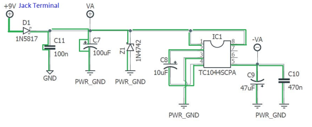
Below is the power portion of the circuit that I have tested for continuity so far. Continuity is the path in GREEN. The only things I found that were unusual to me was that there was continuity across two of the power filtering capacitors labeled C11 and C7 as seen on the diagram below. There was no continuity across the other capacitors (C8, C9, C10) as I would expect.
I was wondering if the power filtering capacitors showing continuity across them may be the source of the short circuit.
It would be greatly appreciated if any of the experts that contribute to this forum have a good method for finding the location of the short on a circuit board. And do you think it may be the C7 and C11 capacitors that show continuity across them?
July 31, 2026 at 5:58 pm #39551brdModeratorI’m not an expert, but I would always suggest starting at the beginning. In this case it is the power supply jack, assuming the wiring is correct, you want to check continuity between the posts, however, because a short anywhere in the circuit would show continuity between the + and – posts you’ll need to disconnect the ground wire from the jack, then with the power disconnected, check continuity between positive and negative posts. if you you have continuity there then the jack is shorted. I would also try removing the charge pump to see if you get normal voltage readings without it in the circuit.
I hope that helps
August 1, 2026 at 4:29 pm #39557Big OParticipantI forgot to add to my original post that the first thing I thought of was a short in the power jack hoping it could be that simple (this is not my first rodeo – I have built over 70 pedals). I replaced the power jack and still had the same problem. That is why I started checking the PCB starting with the power section.
After hours of checking for continuity throughout the board, from component to component and then from one end of a component to another I found out that the only problems were the ones I found above except there was continuity across the LED. I also checked for abnormal grounding for all board components.
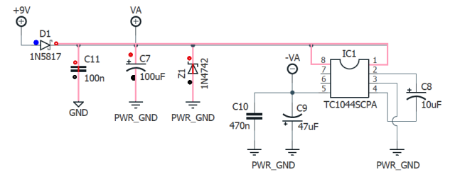
The result was there were definitely 3 and possibly 4 bad components. The C11 power filtering cap, the Z1 Protective diode, the LED and possibly the C7 power filtering capacitor. I replaced C11, Z1 and the indicator LED. I checked everything again and found no shorts. The possible short in the C7 capacitor was due to continuity connecting the positive and neg poles of the capacitor through ground. You can see this in the below diagram where Pink indicates the path to ground and Red is continuity through components when there shouldn’t be.
The pedal powers up and works just as it should. A great fuzz circuit.
August 1, 2026 at 9:03 pm #39559brdModeratorGlad you got it fixed! Testing components in a circuit is generally not the best approach, but you made it work.
-Best
-
AuthorPosts


- You must be logged in to reply to this topic.