
Your Source for DIY Pedal PCBs and NostalgiTone! › GuitarPCB Forum › GuitarPCB Build Support › LFO trouble D.S.O.T.M
- This topic has 3 replies, 3 voices, and was last updated 18 hours, 31 minutes ago by
 brd.
brd.

-
AuthorPosts
-
September 9, 2026 at 2:58 pm #40492GJMParticipant
Hello,
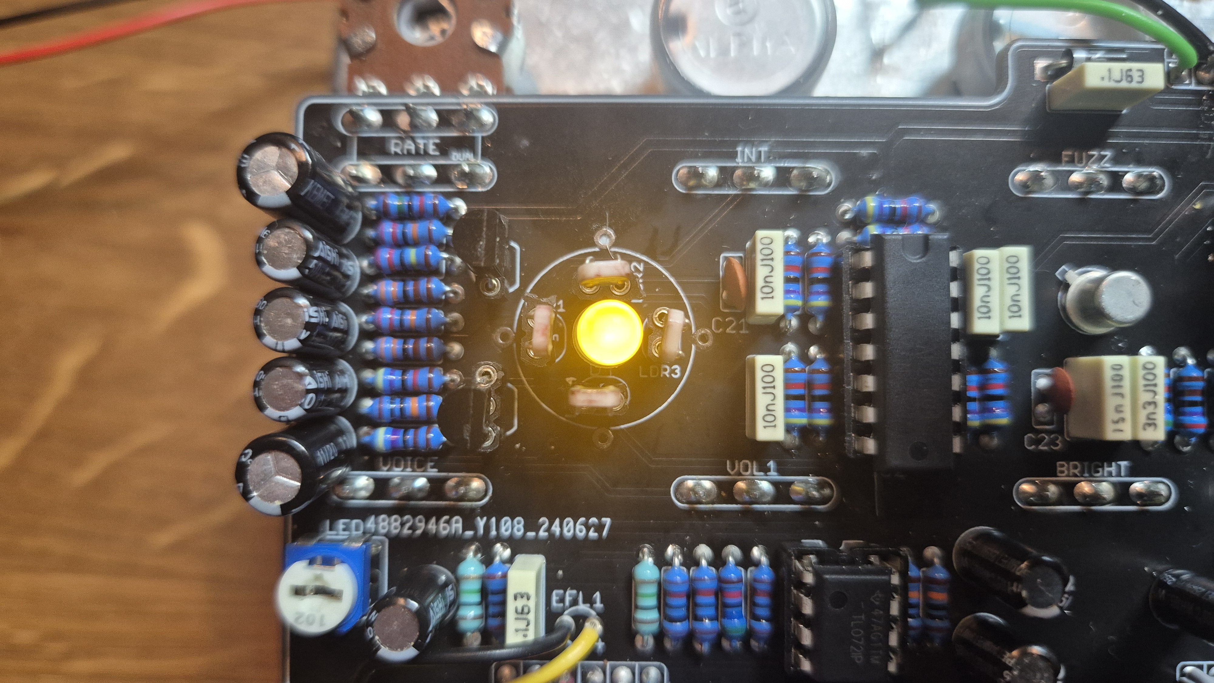
This is probably my first post on a forum ever but I’m afraid I need some help. I finished building the voodoo redux and really enjoyed the build and how the pedal sounds. So I ordered the D.S.O.T.M as a new project from das Musikding. Everything is soldered to the board and the WattAmp and fuzz work as expected but I have some problems with the phaser. The LFO stays “ON”.
I reflowed the solder joints, looked for solder bridges but I can’t find the problem. Voice and Volume seem to be working but not Rate and Int.
I got the following voltage readings from the IC components:TL074
1 4,07
2 4,07
3 4,04
4 8,13
5 4,03
6 4,07
7 4,07
8 4,07
9 4,07
10 4,02
11 0
12 4,03
13 4,07
14 4,07TL072
1 4,06
2 4,06
3 1,88
4 0
5 3,54
6 4,06
7 4,06
8 8,11Maybe someone has some advise for me. Thank you in advance for the support.
Regards,
GJM
 .September 9, 2026 at 4:54 pm #40493BarryKeymaster
The TL074 readings are perfect.
The TL072 (Pins 1 and 7) are sitting stably at 4.06V.
Pin 3 (Reads 1.88V, should be ~4.06V) and Pin 5 is incorrect (Reads 3.54V, should be ~4.06V)
This suggests that IC1 (TL072) could be bad or you have another external component error.
Here are some things to try.
- Swap the TL072: If you have an extra one pull the TL072 and replace it with a fresh chip. This will take seconds. Otherwise..
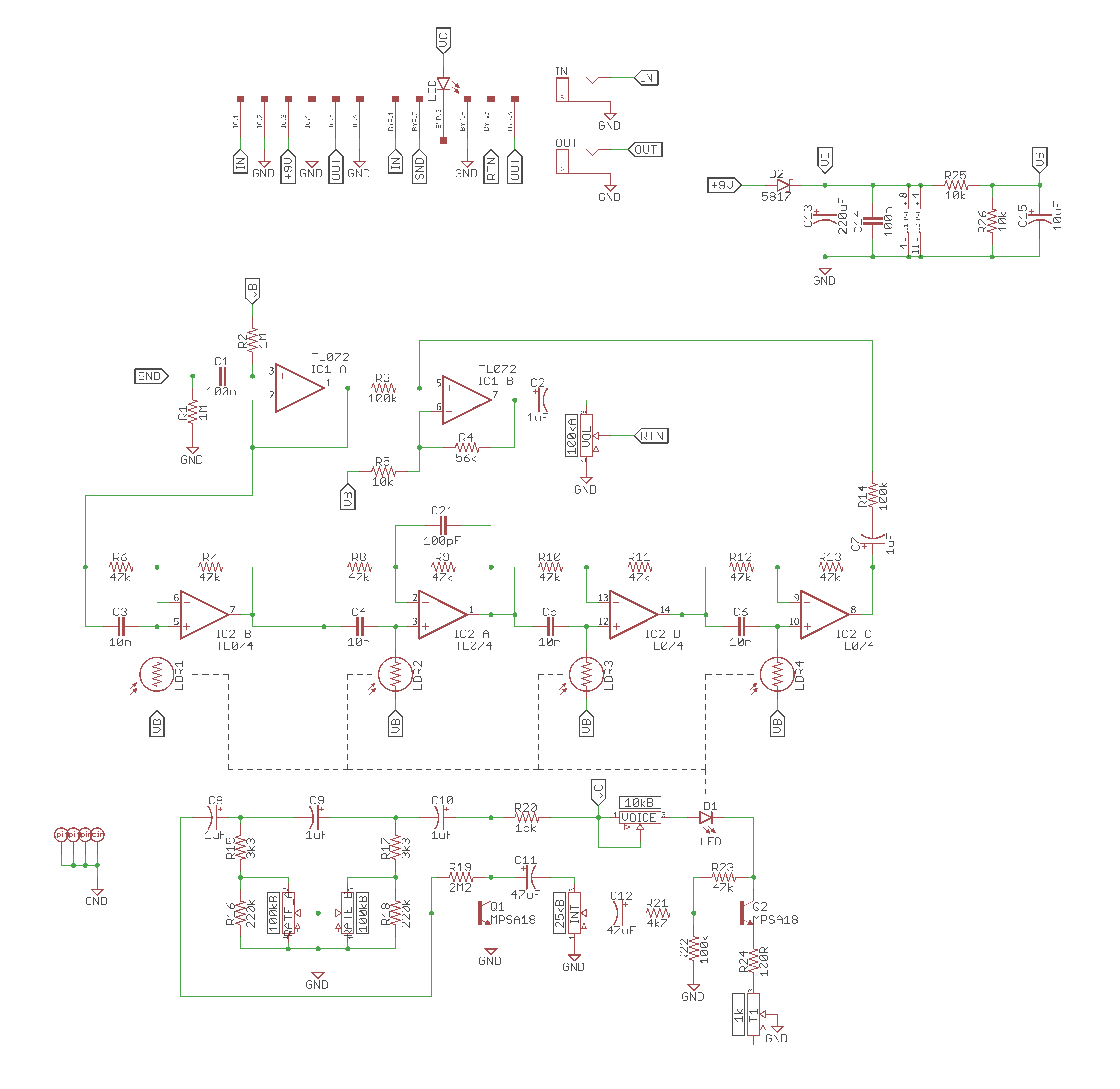
- Check Resistors R1 thru R5: Inspect the resistors directly connected to Pin 3 and Pin 5 of the TL072. Verify by the color bands to ensure an incorrect value resistor wasn’t accidentally installed in the wrong place. A wrong value will drag the pin voltage down exactly like this.
- Look for Solder Bridges on the Pins: Inspect the physical solder joints directly under the TL072 chip. Make sure there are no tiny microscopic splashes of solder connecting Pin 2 to Pin 3, or Pin 5 to Pin 6.
- Remove TL072 and test socket holes 3 and 5. If the socket holes read 1M and 10k respectively with the chip removed, this likely isolates the problem to a defective chip.
Phaser Schematic for convenience and others to chip in.
September 9, 2026 at 6:36 pm #40496GJMParticipantThank you for the quick response and advise. I’ve got some extra TL072’s laying around. I will try tomorrow (it’s after midnight over here) and let you know if it solved the issue.
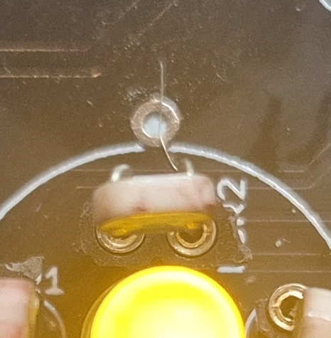
September 9, 2026 at 6:45 pm #40497brdModeratorAfter following Barry’s advice you will most likely have found your problem. If not, do a visual inspection around LDR2. In your picture there looks like a small strand of wire at the base of that component lying across a visa or pad. A stray strand of wire can throw a wrench in the works.
One other thing that I think might be off is the voltage readings on pin 8 of IC1 and pin 4 of IC2. I would expect them to be closer to 9v. I could be wrong, I don’t have one of these boards built to verify. Check your voltage on both sides of D2, R2 and R25 with IC1 removed and see if they change with the IC installed. That could be another indication of a bad IC.
I hope that helps.
-
AuthorPosts



- You must be logged in to reply to this topic.