Your Source for DIY Pedal PCBs and NostalgiTone! › GuitarPCB Forum › GuitarPCB Build Support › No sound and light in LED with MKC v4 with Buffer v3 board
Tagged: MKC
- This topic has 19 replies, 2 voices, and was last updated 1 year, 9 months ago by
 Billy.
-
AuthorPosts
-
September 4, 2024 at 8:01 am #33208AnonymousGuest
As the title says.
I have been building this kit. When I connect guitar and amp, no light in the LED and no sound whatever the position of the footswitch. However in one position I get excessive hum when the volume pot is turned up and if I touch one of the pots the hum increases.
The kit has been build as a stock klon with the exception of adding the bass switch. I have measured the ICs, here are the values:IC2 Measured Measured
1-4.56 4.27 8-9.11 0
2-4.56 4.3 7-4.57 3.82
3-4.56 3.83 6-4.57 3.85
4-0 9.33 5-4.64 4.26IC1 Measured Measured
1-4.57 4.57 8-9.11 0
2-4.57 4.66 7-4.71 1.22
3-3.57 4.66 6-4.57 4.66
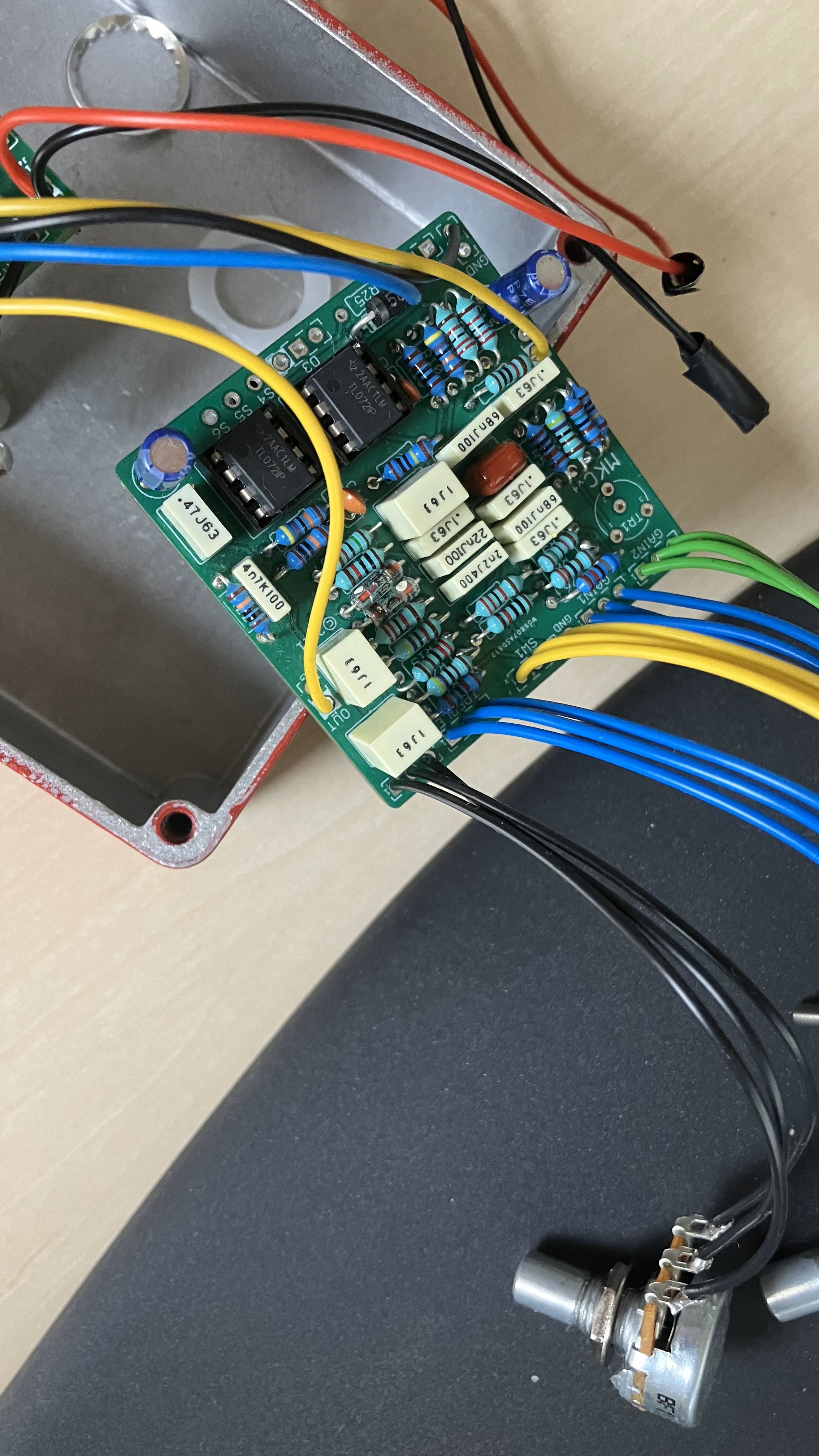
4-0 9.33 5-4.55 4.66Rough pictures of the build below. Any clue? Please let me know if I can take pictures of something specific or if I can measure something else than the ICs. Any help really appreciated.
September 4, 2024 at 10:59 am #33210BillyModeratorCan’t quite see how you’ve got the DC jack wired
Post an image so we can see the face of it and which lugs your 9v and ground wires go to
Because it’s buffered bypass you won’t get anything if its incorrectly wired from your voltages it looks like it may be inverted unless your pin numbers are incorrect this is how it should be connected
September 4, 2024 at 1:42 pm #33211AnonymousGuestThanks for replying. As you can see from the pictures, it should be wired correctly.
September 4, 2024 at 2:33 pm #33213BillyModeratorYes that’s correct is the ground lug bridging the middle battery lug
Are you numbering your IC pins like this
September 5, 2024 at 3:01 pm #33235BillyModeratorFrom your voltages there must be a power issue pin 4 should be 0v and pin 8 power
Are you using a centre negative power supply
September 6, 2024 at 6:10 am #33244AnonymousGuestYes I am using a centre negative power supply. I have also measured the ground and +9V lugs of the plug while the power supply is connected. It reads +9.5 V so all good there. When powering the board for the measurements, I noticed a faint light in the LED. I disconnected the power supply to check it wasn’t some reflection coming from another source. Sure enough there is the faintest of light in the LED when powered on.
September 6, 2024 at 6:35 am #33248AnonymousGuestI think I may have found some problems.
On the buffer board, R1 and R2 measures 500K, and not 1M. I have checked R3 and CLR and they are the correct valuesOn the MKC board I have measured all resistors. R21 and R22 measures 54k each and should be 100k each.
Could these wrong resistors be the problem?
The kit was bought from musikding.de. This is NOT to discredit the guy behind that shop at all! Mistakes can happen. I made several when building this kit 🙂 I work at a company that has its own electronics factory so I will get the correct resistors from there to fix the issue.
September 6, 2024 at 8:51 am #33251BillyModeratorYou can’t really measure resistance accurately in circuit there may be series and parallel resistance connections
When measuring resistance in circuit it should not be powered and you should try to measure resistance from reference points in the circuit for example
To measure R22 value place your meter probes between IC2A pins 1 and 2 you can see from the schematic that between those 2 points there should only be around 100K resistance (we can actually see it is 100K from the colour bands on it)
From the colour bands I can see your values on both pcbs look correct although quite a few of the multiplier bands are hard to see whether they’re brown or red
Use the build doc populated board image to check all values are correct
Time for a quick review I think, your voltages are what’s thrown me I initially thought you had negative voltages with the dash –
What I think you’ve done is simply measured your ICs upside down and pin 4 is actually pin 8
Pin 1 of your ICs is bottom left so your voltages are fine if that’s the case
What are the voltages on the buffer pcb IC
Post an image looking down on both pcbs so that we can clearly see all components and wiring connections it’s difficult to check values and trace your connections with the images you’ve posted
We can’t quite see the connections to your stereo in jack make sure that’s correct and you haven’t accidentally wired your in wire to the ring instead of the tip connection
You can insert a jack and follow the connections around to their solder lugs like this
September 6, 2024 at 2:09 pm #33255AnonymousGuestYou are absolutely right about the IC pin orders. I have remeasured IC1 and IC2 on the MKC board and also IC1 on the buffer board. Here follows the results:
MKC ICs
IC2 Actual Actual
Pin 5 4.64 4.63 Pin 4 0 0
Pin 6 4.57 4.67 Pin 3 4.56 4.63
Pin 7 4.57 4.65 Pin 2 4.56 4.67
Pin 8 9.11 9.35 Pin 1 4.56 4.7IC1 Actual Actual
Pin 5 4.55 4.32 Pin 4 0 0
Pin 6 4.57 4.67 Pin 3 3.57 1.32
Pin 7 4.71 4.66 Pin 2 4.57 4.67
Pin 8 9.11 9.35 Pin 1 4.57 4.67Bufferboard IC
IC1 Actual Actual
Pin 1 0.16 Pin 8 0.01
Pin 2 4.68 Pin 7 9.37
Pin 3 3.12 Pin 6 4.68
Pin 4 0.01 Pin 5 0.16So as you said, IC voltages on the MKC board looks correct with the exception of pin 3 on IC1. Let me know how the buffer board IC voltages look.
Here are some (hopefully) better pictures:
September 6, 2024 at 10:22 pm #33258BillyModeratorCheck IC1 pin 3 voltage with the IC removed from the socket
September 7, 2024 at 3:07 am #33261AnonymousGuestI measured both IC1 on the buffer board and the MKC board as I was unsure which one you meant. IC removed when measuring. Here are the numbers:
Buffer board:
IC1 pin 3: 3.17 VMKC board:
IC1 pin 3: 2.33 VSeptember 8, 2024 at 12:31 pm #33272BillyModeratorYeah apologies I meant the MKC IC1 pin 3, the buffer voltages look OK
I’ve been a wee bit busy so sorry for the delay
Pin 3 on the MKC is low but I notice you get a 1v increase with the IC removed which is still a little low
What voltage do you get both sides of R3 you should have around 4v one side and 3v ish the other side
Check that and then try reflowing it’s solder joints
September 10, 2024 at 12:03 pm #33282AnonymousGuestHi,
Hey no worries, I am so happy that you are supporting me 🙂
I have measured both sides of R3 now. On the left side I measure 1.32 V and on the right side(the side where C14 is closest to) I measure 4.62 V.Still think I should reflow solder on R3?
September 11, 2024 at 4:16 pm #33300BillyModeratorYes late to the party again! Reflow the left side of R3
From your voltages the power supply side is doing what it should you’re just not getting your bias VB to the op amp input pin 3 through R3 obviously it could be something after R3 but hopefully its just a poor solder joint on R3
September 13, 2024 at 11:42 am #33350AnonymousGuestHi,
Sorry for the late reply, been busy with work. So I have resoldered R3 both sides. Still I measure only 1.3 V on the left side and 4.6 V on the right.
September 15, 2024 at 5:44 am #33359BillyModeratorTry swapping the op amps around to make sure IC1 isn’t faulty it doesn’t appear to be with your other voltage readings but worth a check
Reflow IC1 socket solder joints obviously remove the op amp before you do it
September 20, 2024 at 9:50 am #33467AnonymousGuestHi,
Again, sorry for being slow, work, life and sickness came in the way. So I removed IC1, reflowed the IC1 socket , moved IC2 into IC1 and installed IC1 in IC2. Measured R3. Same reading as before, 1.3 V on the left, 4.6 V in the right.
Again sorry for being slow, will make an effort to be faster going forward 🙂
-
AuthorPosts


- You must be logged in to reply to this topic.