@dave-sousa2014gmail-com
Forum Replies Created
-
AuthorPosts
-
September 27, 2026 at 7:13 pm #40694
 SoozayParticipant
Ha! Whoosh right over my head!
I’ll see myself out.
September 27, 2026 at 6:51 pm #40692SoozayParticipantIf only I had the capacity to fight the resistance!
September 27, 2026 at 5:18 pm #40688SoozayParticipantAwesome; that makes total sense re: my results. Thanks for saving me from a futile troubleshooting exercise.
August 28, 2026 at 2:52 pm #40419SoozayParticipantYep, that’s exactly where I’m. Was just wondering if there’s any quirky/fun exploration to be had via rebiasing. If not, it works really well at 5v.
July 18, 2026 at 7:28 pm #39471SoozayParticipantYeah, I had already started to remove the wires after doing some testing and just decided to clip them at that point. I’d definitely start that one over from scratch.
My real concern now is that I fried some components via testing.
July 18, 2026 at 11:44 am #39463SoozayParticipantHa! Apologies on the misidentification, brd! Still have sleep in my eyes (PDT)…
I”m not getting any LED lighting or sound.
July 18, 2026 at 11:06 am #39461SoozayParticipantThanks, Barry. You’re right; appreciate your patience with me.
Regarding D5, I’m thinking now that if I had been multimeter testing the board with live voltage, I would’ve bypassed D5 completely and fried a component or two. Totally on me…
I’ll close this one out and ask the manufacturer if there’s a spare part or two I can buy to fix it v. starting from scratch.
Cheers, and thanks for your help!
July 17, 2026 at 10:44 pm #39458SoozayParticipantThanks, Barry re: the 9V wiring. I’ve ensured that it’s in line with your diagram, and am using a 500 mA isolated power supply.
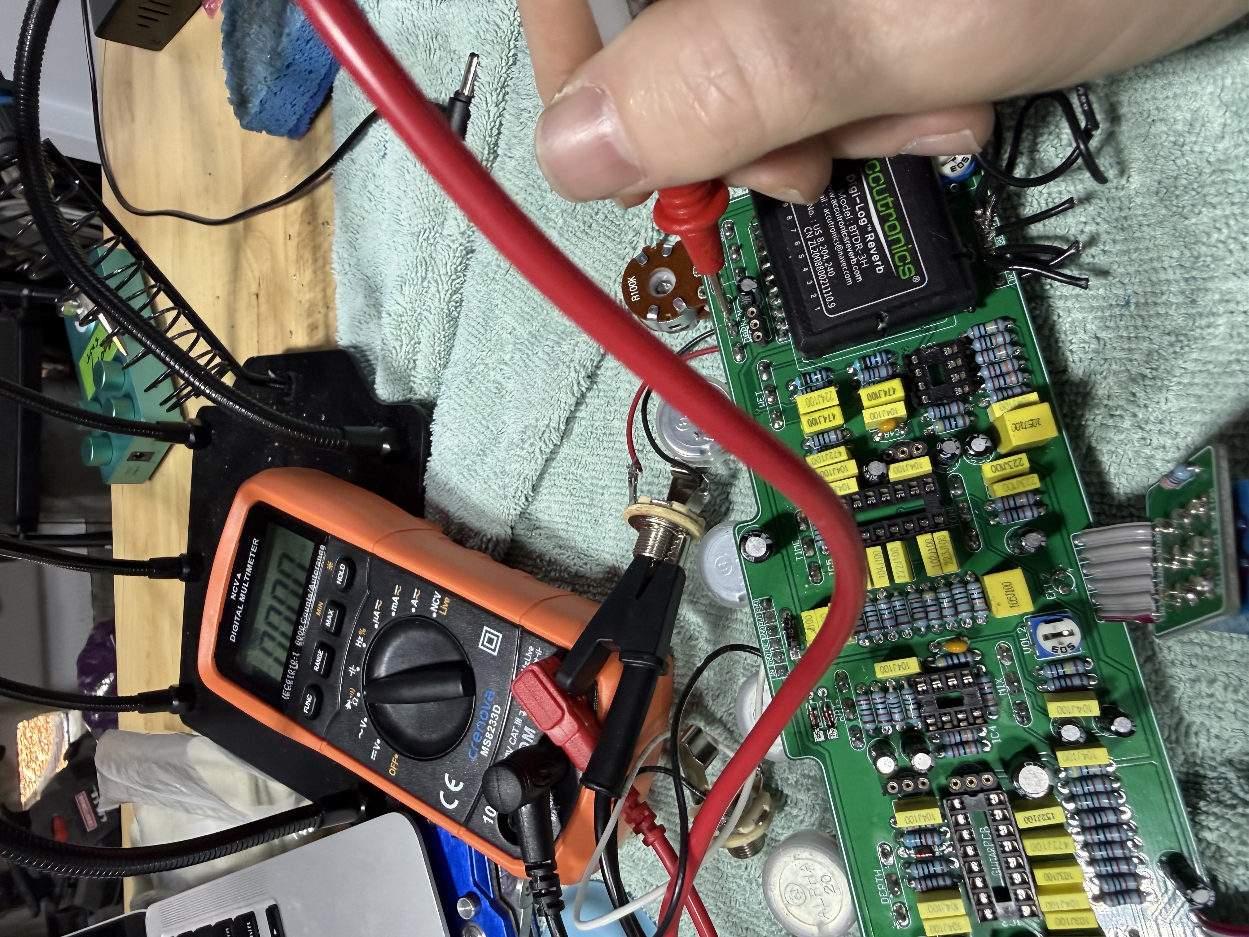
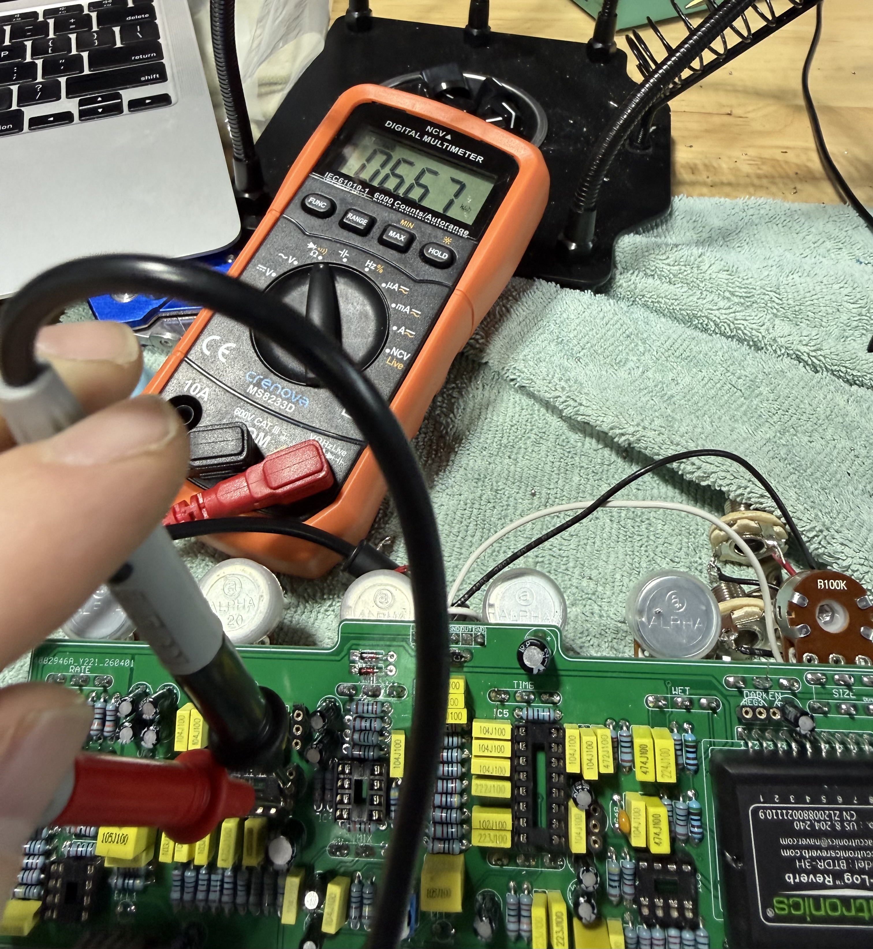
I’ve gone through and reflowed any suspect solder joints and have ensured there’s no solder bridges. I’m at a loss; I’ve taken out all of the transistors and chips and have performed some additional tests. The main 9V power rail is unshorted (measuring 6.6k Ohms at the empty regulator sockets), which should rule out any component assembly errors. However, there is a dead short of 0.0 Ohms between the middle pin of the Darken pot and the ground plane. (I’ve run a continuity test on the pot to ensure it’s in good shape.)
Pics of the readings:
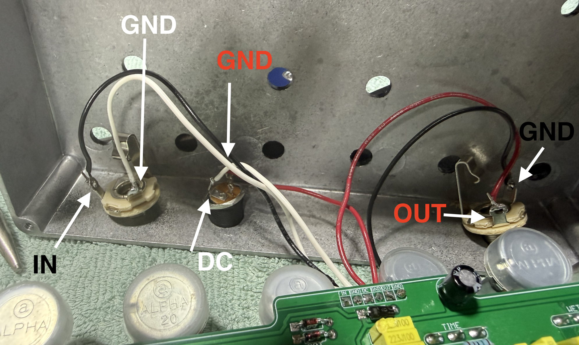
July 16, 2026 at 8:04 pm #39455SoozayParticipantHere’s a diagram of the DC, input jack, and output jack. I’m pretty new at all this and I (admittedly) did a poor job of matching the wire colors to the right use. Font color = wire color. Really appreciate all of your help!
July 16, 2026 at 1:26 pm #39451SoozayParticipantThanks for the confirmation, Barry. I won’t mess with it if it’s benign.
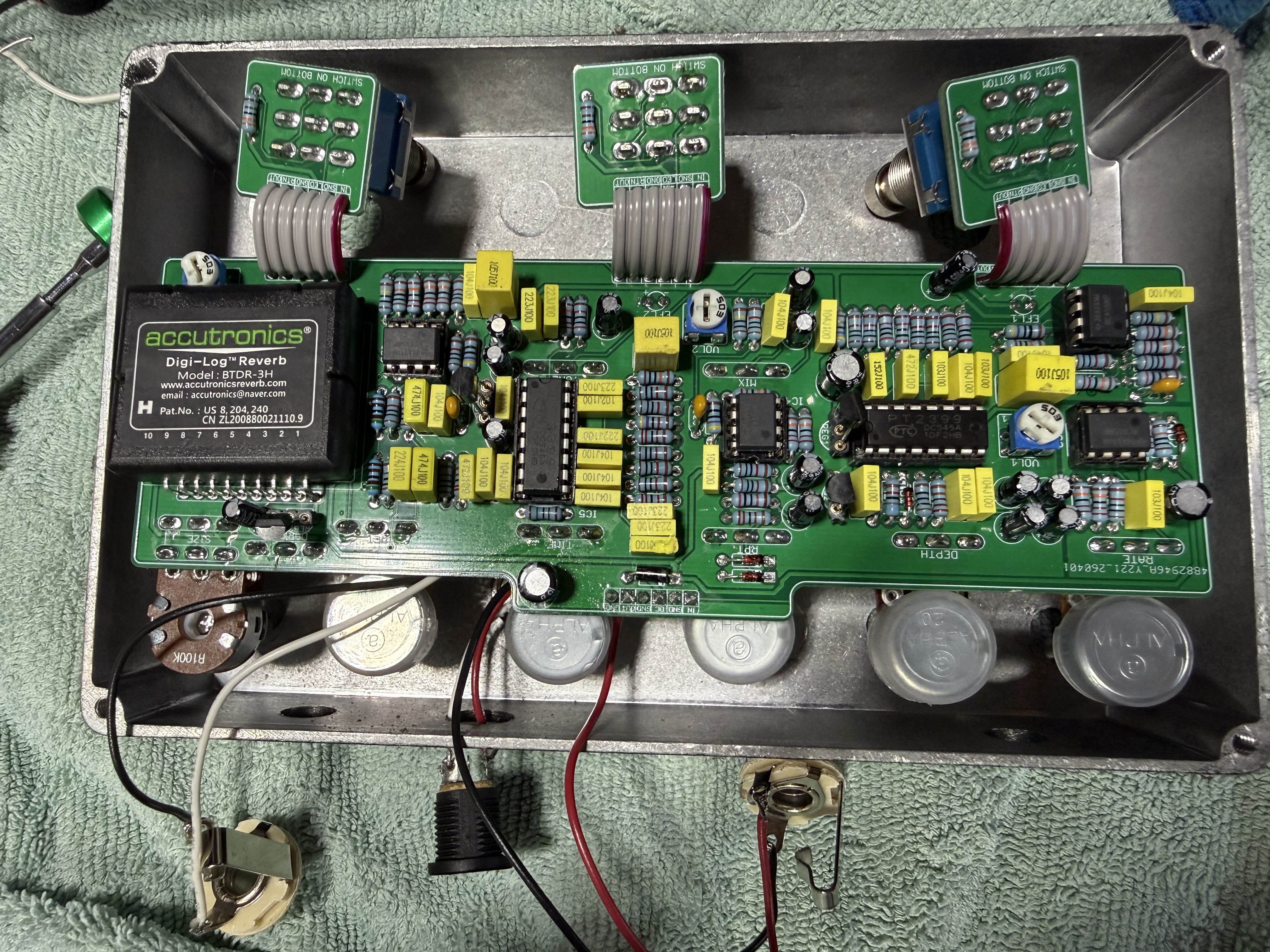
Here’s a pic of the full board:
July 16, 2026 at 12:09 am #39448SoozayParticipantHey, Barry – thx for the response. The line I’m referring to is the vertical line that cuts through the silkscreen borders (and into the PCB surface itself). I’m wondering if it’s a trace cut that’s severed power to the components.
I’ve gone back and rechecked all key components for cold solders, bridges, etc.
Cheers!
-
AuthorPosts