Your Source for DIY Pedal PCBs and NostalgiTone! › GuitarPCB Forum › GuitarPCB Build Support › Mini Me Diagnostic Help (SOLVED)
- This topic has 55 replies, 6 voices, and was last updated 4 years, 8 months ago by
 Cybercow.
-
AuthorPosts
-
April 27, 2021 at 10:08 pm #18458AnonymousInactive
I have a third spare board. I will populate it and roll the dice.
April 28, 2021 at 12:30 am #18462CybercowParticipantI’m unable to determine the BBD chip jumpers. I cannot see that they are horizontal or vertical.
And for clarity’s sake, “continuity” is never tested while the power is on. Only voltage/current is measure with power on. So I’m a it confused by your “With all IC Chips out and unit turned on, there is no continuity from either the bottom pads of R32 or R33 to R1.” and “With all IC chips out and unit turned on, there is no continuity from either the bottom pads of R32 or R33 to pin 5 of IC1.” comment. With over on ,there ought to be ~4.5v at those two points.
And for the life of me, I can’t see anything wrong in the photos. I was hoping to find something.
April 28, 2021 at 1:21 am #18465AnonymousInactiveCybercrow, the BBD jumpers are horizontal per the build document instructions if using the V3207.
I measure continuity again with the power off between the bottom pads of R32 and R33 as well as between the bottom pad of R33 and R1. I do get continuity but when powered on, there is no voltage.
I just completed a third board and it’s a swing-and-a-miss. I still have the same low voltages across the board, dry signal and no modulation. Pics are below of the third board.
April 28, 2021 at 4:14 am #18466BarryKeymasterVerify that you have a 2N5087 in Q1 and not 2N5088.
Verify again that you have 9v minimum at the 9v pad.
April 28, 2021 at 3:32 pm #18472AnonymousInactiveBarry,
I get 8.93 V at the 9V pad. Confirming that I am using a 2n5087 at Q1. These were purchased from Mouser.
April 28, 2021 at 5:01 pm #18475BarryKeymasterCan you share what you are using for your power source?
Like is it a battery and if not what type of power supply etc and any other info that might be different than the norm.
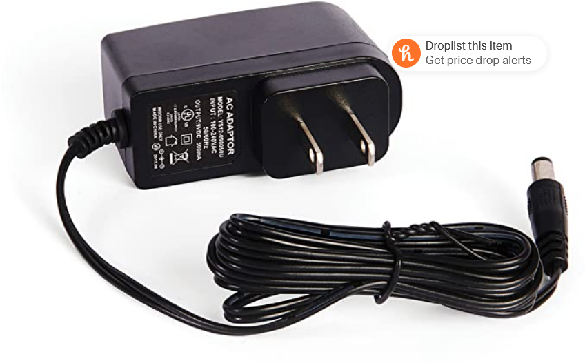
April 28, 2021 at 5:09 pm #18476AnonymousInactiveI am using D’Addario brand 9V wall wart with 2.1mm adapter.It’s as standard as it gets. I don’t use batteries on any of by builds.
April 28, 2021 at 5:16 pm #18477BarryKeymasterIs it this with 500mA max current?
April 28, 2021 at 5:55 pm #18478AnonymousInactiveIt is 1000ma max current.
April 28, 2021 at 9:42 pm #18481BillyModeratorWe know for some reason VB seems to be a problem and the junction of R32 and 33 isn’t giving us the required VB
It’s got to be something common to all builds anyway there’s a possibility of too high a resistance in the voltage divider path so to eliminate that possibility
As you know off by heart now I’d think!
No power to circuit
Check the resistance from the VB junction bottom pads of both R32 and 33 to pin 5 IC1 in each case it should be the the same around the resistor 56K value
You may have to wait for your meter to settle down it will jump around a bit then slow down and eventually stop
The voltages aren’t giving up their secrets so let’s see if resistance won’t resist and give us a clue!
Also check what power is coming out of your adaptor whilst connected to nothing, as you’ll know – simply plug it in stick your ground probe into the centre and touch the sleeve with your red probe, meter obviously set to VDC then plug into your pedal and take voltage on the DC jack lugs and board +9v and ground (I’m a wee bit lost can’t remember if you’ve got it wired to a test box or not) just to see if anything is dropping out, in each case keep your probes on for about a minute to see if it changes
I’ve been down with the flu the last few days defo flu not the dreaded covid thankfully
April 28, 2021 at 10:29 pm #18483CybercowParticipantI’ve measured the current draw on all four of the Mini-Me builds I’ve done so far – and they only draw ~12mA. Even the fifth build, a dual Mini-Me chorus build only draw ~15mA with both boards powered and in use and the LEDs lit up. So current is not an issue. Have you tried with just a fresh 9v battery? About 90% of all cheap wall warts have horrible, (if any), ripple filtering.
But back to original issue of the missing ‘VB’ (1/2 of the main supply) . . . . Either there is a broken trace, (least likely), something is drawing that ‘VB’ voltage down, or it is just not being created at the junction of R32 & R33.
STEP ONE: Now that all the active components are socketed, Remove any power, remove ALL socketed components, REMOVE R1, R17, R34, C13, C14 & C15 (or lift one leg of them). This will isolate the ‘VB’ lines from any leakage to ground. Then measure the values of the following resistors: R1, R17, R31; R32 & R33. If they ALL measure what the BOM says they are to be, then move on to the next step. If NOT, you will have found a problem.
STEP TWO: With power still removed and the above parts still removed (or one leg of each lifted), check ‘VB” points for continuity with a DMM to ensure there is continuity across and to all the ‘VB’ points. Be sure to dig the pointed tips of the DMM leads into the solder for a good connection and get past any flux residue that may remain. If there is no continuity across the ‘VB’ points, a jumper may need to applied to the discontinuous point. Then onto the next step.
STEP THREE: With the above parts still removed (or one leg of each lifted), ADD POWER, change your DMM to measure DC, and meausure the power supply at the junction of R1 & R32 and record it. (With the caps removed, there may very well be some ‘ripple’ on the DC, but that’s OK cuz we’re just going for some rough testing. A battery would be better for these powered up tests than that wall wart.) Then measure the ‘VB’ value at all the ‘VB’ points. By this point, if you have ‘VB’ at all the appropriate places, then it is possible that one of the caps, (C15 is most likely), is bad. If the ‘VB’ is still wrong, I’m at a complete loss. Could possibly be a bad PCB – even after you’ve added a jumper (if necessary) to correct a problem in the continuity step. (It’s rare, but can happen.) If the ‘VB’ is good, then onto the next step.
STEP FOUR: Remove the power, solder C15 (only) back into place; power it up again and measure the DC value on all of the ‘VB’ points again. If the ‘VB’ voltage is still not 1/2 of the supply at the junction of R1 & R32, then C15 is bad. If the ‘VB’ voltage is good, power down, replace C13 (220µF), power it back up and measure the ‘VB’ again. If the ‘VB’ is off again, then C13 is the culprit. If the ‘VB’ is good, then power down, replace C14 (10µF), power it back up and re-measure the ‘VB’ value. If the ‘VB’ is off again, then C14 is the issue.
By now, I believe you see how this works. By isolating the questionable supply line and doing some rudimentary checking, we are replacing components one-by-one to what is causing the ‘VB’ to fail. So after going thru all the “power down, one-by-one component replacement, re-powering, and measuring” steps for each part involved in the continuity of the ‘VB’ lines, one can eventually pin-point the problem.
Once you’ve gotten to the point where all the resistors and caps are fully installed again, and (hopefully) the ‘VB” is stable, RINSE & REPEAT the “power down; replace just one of the socketed parts, power back up” process (and measure the ‘VB’). If the ‘VB’ fails again after putting in one of the socketed parts, then the problem is narrowed down tremendously.
I know all these tedious steps can be a PITA, but it’s what troubleshooting is about – a slow methodical process – but it yields results.
Please keep us appraised.
April 29, 2021 at 3:00 am #18487AnonymousInactiveBilly, thank you for your input. I am sorry to that you were affected by the flu but am relieved it was not Covid. Thankfully I have been able to work from home since March of 2020 and am somewhat introverted. I have asthma and frequently get viral bronchitis; the prospect of contracting Sars-CoV-2 scares me if not for the possibility of the nerve damage it can cause from inflammation. Stay safe, stay healthy.
Cybercrow, I tried a battery but no dice. I am going to take a break from this for a few days. With my luck, it might be quicker to wire up another board sans the components that could cause VB leakage to ground and go from there.
May 11, 2021 at 4:36 pm #18678AnonymousInactiveI am taking a break from this build and have every intention of returning to it. That said, I must remark that I can not tell if Barry is making fun of me, promoting the 12th anniversary of GuitarPCB, or both! ?
May 11, 2021 at 8:59 pm #18683BarryKeymasterMay 23, 2021 at 12:21 am #18860AnonymousInactiveGood news: i sent my second and third boards to a gentleman who knows what he is doing! He confirmed there was nothing out of the ordinary with my board or my soldering work on them. He further confirmed the LM358 and CD4047 i used were bad ( I had purrchased these from a reseller on Amazon). With replacements, they are working.
The odd news: Cybercow- I built up a fourth board with sockets for all ICs and transistors. I purposely left out . R1, R17, R34, C13, C14 & C15 for the purposes of following your instructions (which I greatly appreciate you taking the time to write).
Step One: I measured R1, R17, R31; R32 & R33 and they all reflected the values stated in the BOM. Check.
Step Two: I set my DMM to continuity mode and checked for continuity across and to all the ‘VB’ points. i got my 0.00 reading on all VB points. Check.
Step Three: I hooked a 9V pad and a Ground pad to a battery connecter. Next, I set my DMM to read DC. I got 7.66V at the junction of R1 & R32; a little low but OK, I’m expecting half this at the VB Points. Then I measure, the VB points….
Note: C15 was installed before I took the photo. I got the same reading at still when C15 was left out of the board.

i have to admit I am really, really confused about the non-existent VB; especially in light of the fact that builds 2 and 3 are confirmed operational and the fault lied with bad IC chips.
May 23, 2021 at 11:17 am #18862CybercowParticipantPaul – you said: “Step Three: I hooked a 9V pad and a Ground pad to a battery connecter. Next, I set my DMM to read DC. I got 7.66V at the junction of R1 & R32;”
The junction of R1 & R32 should be the +VB (1/2 of the supply voltage) there is something still amiss. To be sure, the junction of R1 & R32 should include R33, the + side of C15, R17, and pin #5 of IC1(B).
And for grins & giggles, I would leave the “G2” point disconnected for this +VB testing. “G2” is the LFO ground and nothing in the LFO section should have any bearing on the +VB supply.
Man, you’ve got me scratching my head again too.
May 24, 2021 at 12:44 am #18870AnonymousInactiveFace in palm. Here is a video confessional for all who followed this thread.
-
AuthorPosts


- You must be logged in to reply to this topic.