
Your Source for DIY Pedal PCBs and NostalgiTone! › GuitarPCB Forum › GuitarPCB Build Support › Bass Overthruster problem (solved)
- This topic has 23 replies, 3 voices, and was last updated 3 weeks, 3 days ago by
 John Kallas.

-
AuthorPosts
-
September 26, 2026 at 5:20 pm #40652John KallasParticipant
i just finished building the Bass Overthruster but there’s a problem with the drive control. whenever i try to turn it past 1/2 way the clipping leds pulse back and forth and the signal cuts in & out with the pulsing. i thought that they should light up in unison and just get brighter when the gain increases (more distortion). what’s going on here? I triple checked my build and there aren’t any cold or missing solder connections or wrong parts placements.
HELP!!!! i want to get this circuit working properly!
September 26, 2026 at 5:25 pm #40656BarryKeymasterSo one step at a time.
Before I ask for photos and voltages, the first thing based on what you are saying that I want to know is are you using an Active Bass?
September 26, 2026 at 5:39 pm #40657BarryKeymasterWhile I wait for your response, and since I will be going out soon, I will address a couple of things.
The behavior of the two clipping LEDs is normal. D3 and D4 are wired in opposite polarity, so they respond to opposite halves of the signal waveform. They are not intended to light in unison.
The part I want to investigate is the signal cutting in and out when you increase the Gain control. You mentioned that everything else is working properly, so before we start looking for bad components or solder joints, I have an additional question:
When the signal cuts out, does it come back immediately when you turn the Gain back down, or does it stay out until you play another note?
If you can, let me know what the input source is, active or passive, and exactly what happens as you slowly turn the Gain control from minimum to maximum.
September 26, 2026 at 5:58 pm #40658John KallasParticipantthanks for the reply. i’m using passive basses. and yes, the signal comes back when i turn the gain down.
September 26, 2026 at 6:07 pm #40660BarryKeymasterOkay, that’s helpful. Since you’re using a passive bass and the signal comes back when you turn the Gain back down, let’s start with the obvious things before getting into troubleshooting.
First, please post a clear, well-lit photo of the top side of the PCB. Try to get the entire board in focus and close enough that I can clearly read the resistor color bands and see the component placement. I want to double-check the resistor values and make sure everything appears to be in the correct location.
I was just playing mine earlier today using an Active Ibanez.
Also, when you slowly turn the Gain up from minimum while playing, approximately where does the signal start cutting out in the rotation?
Are you using a C Taper 500K pot?
Does it happen at the same point every time?
September 26, 2026 at 6:25 pm #40662John KallasParticipanti have to get ready for a gig so i won’t be able to reply until later tonight. i’ll post pics when i get back home. thanks!
September 26, 2026 at 6:37 pm #40663brdModeratorI’ll watch for a reply. go melt some faces.
September 26, 2026 at 9:49 pm #40664brdModeratorI’m on EST, I’ll check back in the morning.
I’m curious what color LED’s you used, and if they were anything special like super-brite or ultra-brite.
If you used a socket for the op-amps, I would suggest trying another TL072 if you have one handy, just because it’s easy.
September 27, 2026 at 2:40 am #40667John KallasParticipantokay, i just got back home from the gig. i did try another TL072 but it still had the same issue.
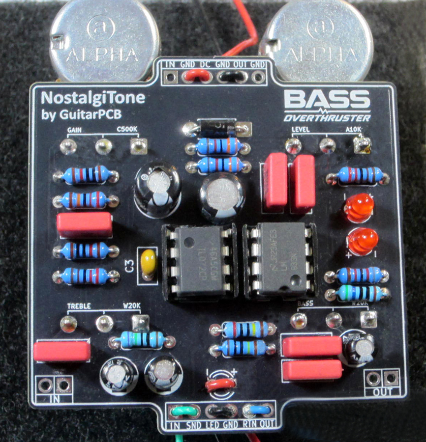
September 27, 2026 at 2:54 am #40668John KallasParticipanthere’s pic of my pcb. (don’t mind the jumpers on the ins/outs, status led and + & – wires, i just use them as stress reliefs when mounting and using a relayed true bypass.
September 27, 2026 at 2:58 am #40669John KallasParticipantyes a C500K pot with red leds as seen in the pic above. the problem is at approx 1/2 way on the drive pot
September 27, 2026 at 3:53 am #40670BarryKeymasterThanks, I looked over your build and everything appears to be correct from what I can see, though be careful if the potentiometers do not have a protective backing on them which I cannot verify from the photo.
I do have one suggestion that may be worth trying, especially if you’re using higher-output pickups or prefer a pickup height closer to the strings.
It’s possible that the signal level going into the clipping section may simply be a little hotter than the circuit is expecting. R6 controls how hard that section is driven, so increasing its value may reduce the loading and clipping intensity.
If you have an 8.2K or 10K resistor in your parts bin, I’d try one of those in place of R6 and see if it changes the gain-drop behavior. This isn’t a confirmed diagnosis, but it would be a quick and simple test to see whether the input level/clipping section is what’s causing the problem.
If it doesn’t make any difference, we’ll know to look elsewhere.
September 27, 2026 at 5:58 am #40673John KallasParticipantok. socketed R6 and tried a few different value resistors in it. a 4.7k still did the pulsing as well as a 6.8K. the 8.2K did cure the led pulsing but it needs to have the gain control up to 70% of it’s rotation to have a fair amount of distortion and at 100% it’s there’s not all that much more (at 50% the pedal is louder but still is clean. i was hoping that this pedal would get dirtier than this, but i guess it is what it is. it does make me wonder if a C1Meg drive pot would get it where i want it to be
thanks for the help with this.
BTW, i also have a Powerstage PCB that is nearly an identical circuit with only a couple of cap value changes so i’m wondering if it’ll experience the same issue.
john
September 27, 2026 at 6:44 am #40675BarryKeymasterI do not have an issue with either circuit with any of my instruments. Of course, different instruments, pickups, pickup height, etc. can all affect how hard a pedal is being driven, each in their own way. The intent was to have a powerful circuit that works in tandem with the amplifier gain, so not having a ton of distortion until the Gain is fully cranked was intentional. That said, I am going to test 8.2K and see how I like it. I may go with that instead to ward off any future issues.
I am glad you’ve now got the original problem sorted out. Increasing R6 to 8.2K stopped the signal from cutting out, but the trade-off is that you now have less available distortion through the rotation of the Gain control which makes sense.
If you want the pedal to break up earlier while keeping the 8.2K R6, you can simply change the clipping diodes. The LEDs are used purposefully in this circuit to create a Bass Drive that does not distort right away.
You can remove the LEDs and use 1N4148, 1N914, etc. instead. This will give you faster breakup and more available distortion. The trade-off is that you will lose some volume, but that shouldn’t be an issue (just turn the Level up). You could also experiment with a C1M Gain pot if you want to change the way the gain comes on through the rotation, but I would definitely try the diode change first.
So at this point, you’re simply tailoring the distortion and Gain response to your liking, and I would start your experiment with the clipping diodes.
I wrote this Clipping Guide which is very applicable to this exact situation. That should help you dial it in just the way you like it.
September 27, 2026 at 12:56 pm #40681John KallasParticipantyeah, i was thinking about changing the leds with 4148’s for more dirt. thanks for replying!
September 27, 2026 at 1:17 pm #40682John KallasParticipantjust tried it with 4148’s and the dirt cutting in & out (pulsing) is back and that’s with the 8K2 resistor, so i’m going to reinstall the red leds.
September 27, 2026 at 4:05 pm #40684BarryKeymasterI honestly cannot explain that.
The other option to increase distortion with the Red LEDs back in place (verify they are working first) is to increase R5.
You can try 470k.
-
AuthorPosts


- You must be logged in to reply to this topic.