Your Source for DIY Pedal PCBs and NostalgiTone! › GuitarPCB Forum › GuitarPCB Build Support › The Vibe v4 pain
Tagged: Vibe
- This topic has 15 replies, 7 voices, and was last updated 2 years, 7 months ago by
 Anonymous.
-
AuthorPosts
-
April 9, 2023 at 1:12 pm #28237AnonymousGuest
Hello everyone!
I read some others had issues with The Vibe, I purchased some days ago the kit from Musikding. No sound, just a very very low fuzz with a taste of phaser, but nothing good.
First I saw that transistors are flipped respect what reported in the PCB, and that’s ok (they are 2n5457). Then I saw that the zener diode is reported in two different ways PCB is opposite than what designed in the reference scheme in the instruction sheets. So I tried both, same result. I tried different connections (ground and 9v) but still no sound.
Just to add, I modified the pedal with the 90/45 mod (added the on-on switch), which affects the noise, I can hear a difference in the two settings. I also modded the main switch adding a momentary second one. Tried to turn the trim carefully all the ways but nothing.
I see that leds are working fine and bypass is normal.
Any ideas on how to test?
(nice to know also that I am a noob in electronics, I just have fun soldering and mounting stuff following instructions, the most advanced trick I can do on my own is change a resistor to smooth a led, so please be kind 😀 )
thanks a lot in advance!April 11, 2023 at 8:58 am #28261mybudModeratorWelcome Fabio!
A couple of things to check. I assume that:
- your 5457s are a matched set
- each of them is sitting correctly in the sockets (try gently moving them in testing)
- you’ve connected both grounds (if not, the pedal won’t function correctly).
It’s also worth connecting R32 or at least bridging it if you’ve made other wiring arrangements. I suggest you try each of these in order and see if one change at a time makes a difference.
April 11, 2023 at 9:01 am #28262mybudModeratorAn afterthought. Check this link:https://guitarpcb.com/wp-content/uploads/2021/09/The-Vibe-v4-2021.pdf and verify that you have the affected diode the right way round.
Good luck. Let us know how things go.
April 11, 2023 at 10:06 am #28263AnonymousGuesti think the orientation of some of your transistors may be backwards.
April 11, 2023 at 11:55 am #28267mybudModeratorHi @sofnwhat: They are 5457s, so the pinout should be reversed from 5952s, I believe.
April 12, 2023 at 11:47 am #28279AnonymousGuestHello again and thanks first of all.
well, today I “refreshed” all soldering points that seemed to me too light. Bypassed the switch on/on selector but nothing changed. All grounds are connected and tested. Nothing changed
the only idea I have is to bypass the momentary switch but I don’t know if it can be a good test.
I would like to know if there is a reference somehow to test the ICs, I don’t know where to point the pins to check the voltage.
Any other idea?
April 12, 2023 at 10:56 pm #28291BarryKeymasterWhen you are just starting out it is best to build stock first to make sure everything works before adding on mods. I cannot tell by the photo provided what the switch wiring looks like. I would remove it and build it stock. Also, we cannot see the back of the board or the off-board wiring to jacks etc. This is why it is extra hard for us to make a suggestion.
April 13, 2023 at 10:00 am #28292brdParticipantIt is nice to have an audio probe to be able to trace the signal path. I think it’s one of the best tools to isolate issues. By being able to verify a good audio signal at the input to the board you have a quick way to know which direction to go with testing (usually). It can also help locate problems on the board by following the audio path on the circuit.
For safety and simplicity, I use a 9v battery powered amp for bench testing. If I need an audio probe, I can clip it to the output jack on the build and test away using the amp to listen.
You can do some damage with a probe so be aware of what you touch with it.
April 13, 2023 at 5:15 pm #28296AnonymousGuest@mybud, R32 is the current limiting resistor for the onboard LED, D2, which is unpopulated in his build, likely because he’s using a 3PDT wiring board that contains a location for the LED and CLR. Obviously Pads S4, S5 and S6 are also unpopulated in the build image.
Kit providers like Musikding, Pedal Parts Austrailia and Pedal Parts and Kits (my company) may include instructions to leave this empty since a 3PDT wiring board is included with the kit and the onboard LED feature on The Vibe PCB remains unpopulated. Adding a resistor or a jumper to this location does nothing when the onboard LED is not used. One of my customers read your post and requested that I send this resistor.
Below is the standard blurb which was a staple of every GuitarPCB.com build document for years. This one was customized specifically for The Vibe and came out of an older version of the build document. This was removed in newer versions of the build documents, but remains valid today.
April 14, 2023 at 6:17 am #28302mybudModeratorSure, @Bruce R, understood and noted. I also have an older revision of the board which may have complicated things, but note that this aspect hasn’t changed in the new revision: the need for connecting both ground pads. Can’t see from the pic whether or not this is in place.
April 14, 2023 at 8:08 am #28303AnonymousGuestI agree a better picture of the wiring would help a lot.
April 15, 2023 at 5:19 am #28317AnonymousGuesthello folks and, again, thanks a lot for your suggestions.
Here’s the back of the mainboard, and a larger view with the wiring.
Here’s a link to a sample audio, first two notes in bypass, than switching on and begins the sufference; I just added a bit of limiter/compressor to level the peaks, for a better un-pleasure to listen to, without turning up and down the volume, by the way the clipping is made by the pedal not by the limit/comp post processing.
When you hear the distorted sound I was beating the keys like a carpet, otherwise it barely produces any audible sound.
Just to let you know. Yesterday I wired again the switch, changing it and not using the switch pcb, linked directly the potentiometer to the board, but nothing again. R16 and R32 have that long legs resistors because I was trying to solder it in the basic way, excluding possible mod errors, but nothing has changed.
Tried to link the grounds (G and G2) in different ways, and all sound linked (with the tester).
Funny detail, I have the same identical sound even if I unplug the transistors..
April 16, 2023 at 7:26 am #28328mybudModeratorYou’re very welcome. The suggestion regarding R32 was clearly a senior moment on my part, apologies.
I’d try the following steps:
- Double-check all component values in case there’s an incorrect cap or resistor value that’s crept in somehow
- If all of these check out, try gently cleaning the solder side with isopropyl alcohol. As far as I can see, the joints look good (no dry joints or other issues), but it doesn’t hurt to give it a good clean in any case
- Try bypassing the footswitch and connecting your ins and outs direct to the board (use alligator clips). If that works, then you’ve eliminated the footswitch as a possible problem. Not common, but possible
- Finally, if you’ve eliminated all these possibilities, try slowly adjusting the trimmer. In my experience, there’s a quite narrow band within which you get the most phasing with least distortion.
Listening to the audio, that kind of weird ring modulation sounds like the trimmer’s off somehow, but I’m baffled as to how it can sound the same without the transistors in place. Make yourself an audio probe and work stepwise through the audio path till the problem reveals itself. Let us know if there’s progress.
April 16, 2023 at 9:17 am #28330brdParticipantOkay it’s a little early yet but I didn’t see any notes in the new build doc regarding the trimmer and adjustment. For that you should start around mid-sweep on the trimmer and make very small adjustments to find that spot.
Another basic question is, are you using a known good power supply?
The troubleshooting could be getting more technical from here. Do you have a Digital Volt Ohm meter?
April 17, 2023 at 9:16 am #28340BillyModeratorIt sounds like something is mis biased
Post the voltages for all transistors and ICs
Q5 pins are C, B, E (collector, base, emitter)
https://www.componentsinfo.com/2n3906-transistor-pinout-details-equivalent/
Q1 to 4 pins are D, G, S (drain, gate, source)
https://www.componentsinfo.com/2n5457-transistor-pinout-equivalent/
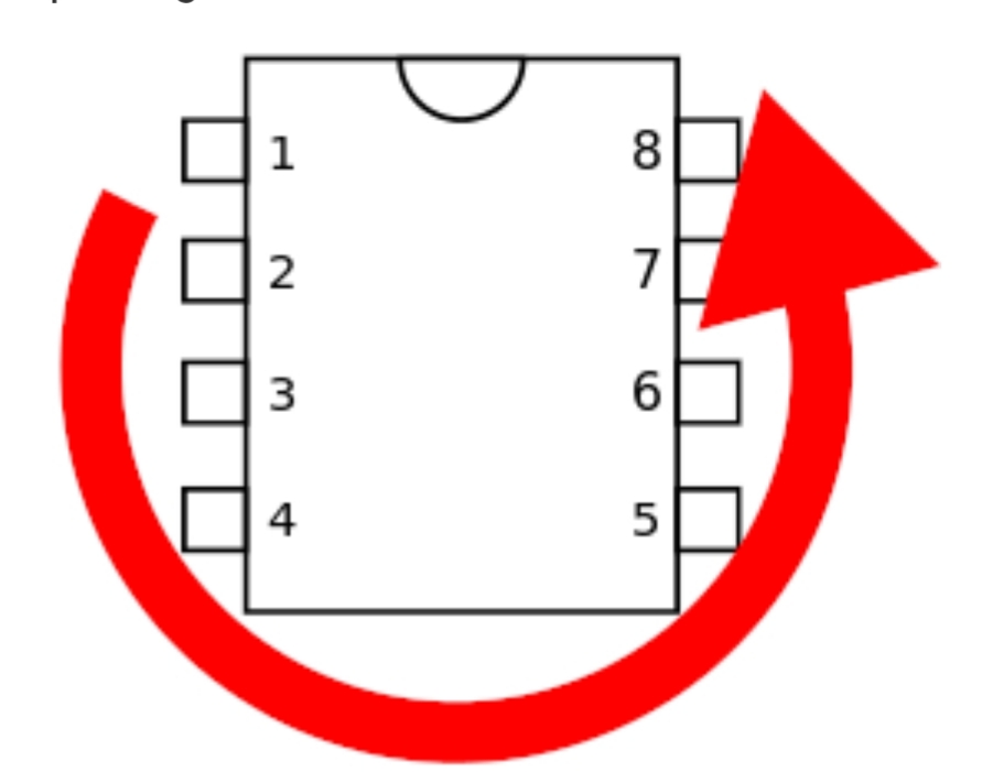
IC pins are numbered from the dot or notch pin 1 down and up and around in a U shape like this
The phasing sweet spot is around 2.2 to 2.5v on the FET gate pins set using the trimmer, all gate pins are connected as you can see in the schematic so you’d only need to set voltage on one then obviously check they all read the same
As far as I can see all your component values and orientation are correct
If you’re unsure how to check voltages using your meter set it to 20v DC place your black probe on a ground point and your red probe to each transistor and IC pin
November 24, 2023 at 4:43 am #30185AnonymousGuesthello everyone,
I come back to this post because after some months of “trying to forget my unsolved troubles” I returned to that project and found out that the TRIMMER had a text “250” on the side. I had a light bulb flashing: measured the voltage going after the trimmer and it was weird, measured the trimmer itself and it was 250 OHM, not 250 Kilo OHM! the guys from Musikding are cool rocking people, I love them so much but sometimes the stuff in the kit has to be carefully checked.
Now, trying with a potentiometer which has the same value, all works as expected and I can start modding with both the mod purposed for all document versions I can find (one here, the other one from musikding website. Regarding this, I suggest you to update the V4 document with all the mods)
thanks so much everyone that replied -
AuthorPosts


- You must be logged in to reply to this topic.