@mixgtrz
Forum Replies Created
-
AuthorPosts
-
January 12, 2026 at 7:11 pm #38208
 MixGtrzParticipant
Thanks again guys.
And particularly the troubleshooting process laid out by playsforfun. It’ll take me a while to get what I need and run through the steps, but I’ll report back once I have.Cheers,
MickJanuary 12, 2026 at 12:54 am #38204MixGtrzParticipantHi All.
Sorry for the delayed response. Had other priorities unfortunately.
Anyway…
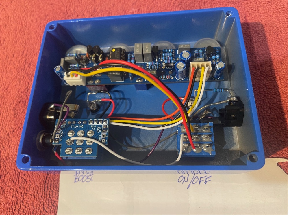
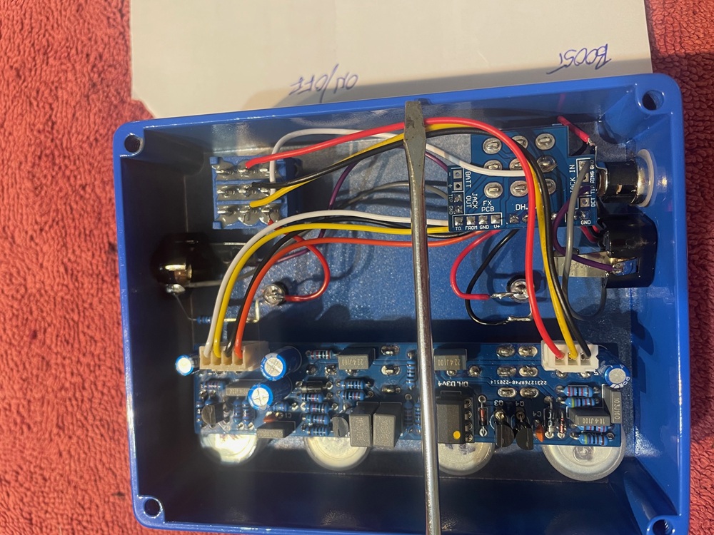
re: playsforun, I’ve post two new pics of the wiring per your suggestions.
re: brd, I know the boost section is working but have tried every possible order of the 3 wires on the common lugs of the on/off switch with no success. Also worth noting that the boost switch is the one with the 4 wire connector and goes the input of the main board (V+, GND, FROM, TO)I’m open to more suggestions but may need to find/hire a local EE to help me. This could become the most expensive kit build in history!
January 8, 2026 at 7:25 pm #38189MixGtrzParticipantWell, still no joy…
I tried the suggestions that playsforfun offered, but it’s not working. However a slightly different result than the first one.
The on/off switch still does nothing (LED comes on). Just bypasses the signal. However with the Boost switch on, the master volume, tone and overdrive work (as you’d expect) but the boost level pot does nothing.I’ve tried changing the order of the 3 wires going to the on/off switch, as well as moving to lugs 7 8 9, and no change in function.
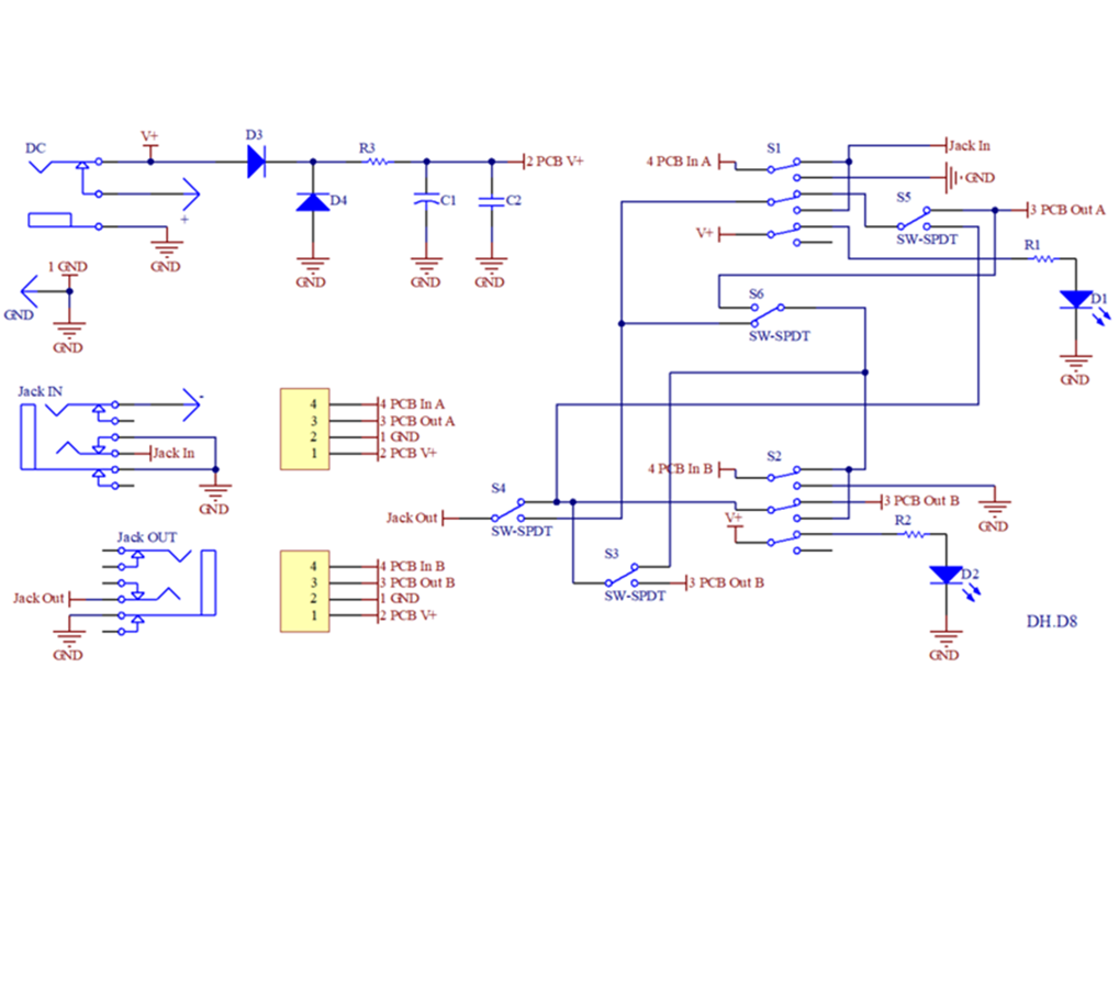
I think understanding the dual footswitch pcb scheme is critical here (which I don’t!). I’ve tried following the traces to map it out but get lost trying to relate it to the fx pcb.This has a lesson in just how much I don’t know…
January 4, 2026 at 11:07 pm #38170MixGtrzParticipantThanks again mate. That’s very helpful. I’ll wire it up as described and see how it goes.
re: power for the boost LED, there is a trace on the dual FS board that runs across from lug 2 of the boost switch to lug 2 of the on/off switch. When I apply power to the board, I get 9v at those lugs so I’ll try that after I get the FS’s functioning.
Also the FS board has the CLR on the switch side of the board. It’s kind of weird as the resistor is kind of stood up on one end!
I truly appreciate your help.January 4, 2026 at 6:35 pm #38167MixGtrzParticipantThanks Playsforfun.
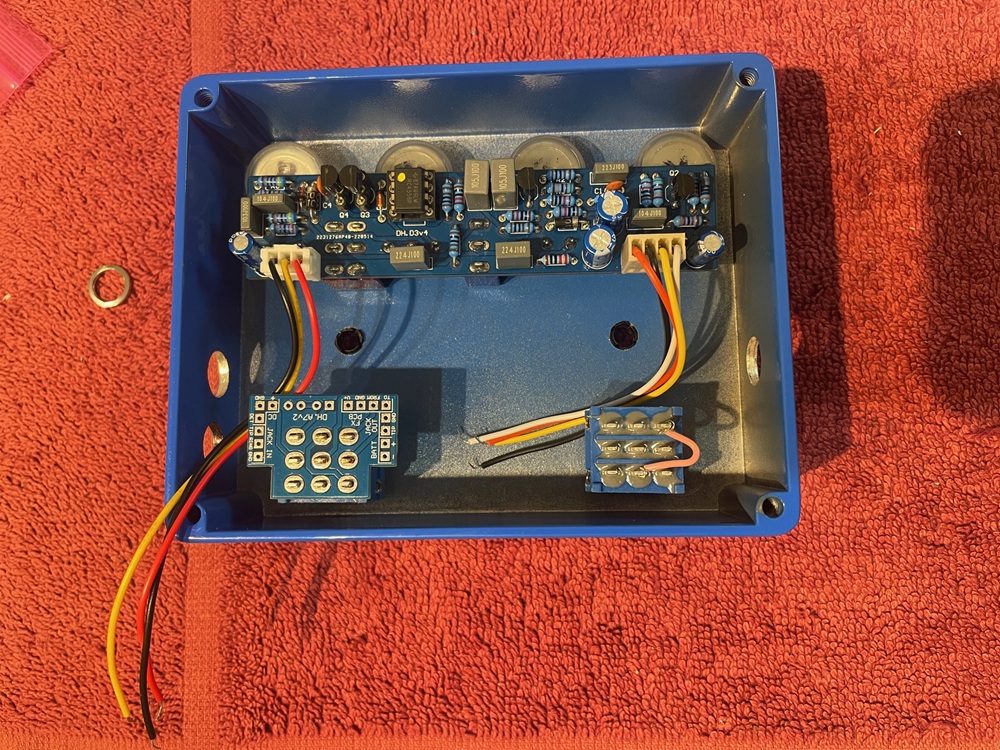
I’ve attached a photo of what I’m working with. I have two 3PDT pcbs, but assumed I only need the one (shown on Boost).
The 4 wires coming off the main pcb would presumably go the corresponding points on the switch pcb (V+, Gnd, From, To) (labels on main pcb on other side) but I’m at a loss as to how the two switches are connected together (particularly power for on/off LED an output jack).
I *think* the 3 wire connector goes to the three common lugs of the on/off switch. From top down (lugs), would go Red (4), Yellow (5), Black (6) and a jumper from 7to 6.From there, I haven’t a clue. And may be completely wrong on the above.
January 3, 2026 at 8:27 pm #38161MixGtrzParticipantThe switch schematic doesn’t appear to have uploaded, so have reposted. Thanks!
October 28, 2025 at 6:09 pm #37722MixGtrzParticipantThanks BRD.
I guess swapping chips is technically a mod, but it almost doesn’t feel like it because it’s so easy to do (providing they’re socketed).
I don’t have any problem removing/replacing them, and I didn’t even know there was a tool! (apart from me!)I’ve had that “life of pots” article bookmarked for about 20 years! I’ve referred to it many times over that time.
I can’t tell you how forums and threads I’ve seen it posted in! Good to see it still being used.October 18, 2025 at 6:43 pm #37631MixGtrzParticipantThanks for your reply Billy.
I’m just using the red LED that was included in the kit. It’s just an opaque red one. I have no idea what the mcd brightness is but it’s not like some of the water clear coloured ones that will burn out your retnas!I also have used a 10k CLR with some other pedals, but I’ve tested the kit one with a 1k8 and a battery and it’s not very offensive.
Thanks again!October 5, 2025 at 9:07 am #37542MixGtrzParticipantThanks Playsforfun! That’s exactly what I needed.
I’m contemplating an external switch instead of the DIP, but not 100% there yet.
I’ve seen some other posts detailing the wiring for it. More research to come!Cheers,
Mick -
AuthorPosts