Your Source for DIY Pedal PCBs and NostalgiTone! › GuitarPCB Forum › GuitarPCB Build Support › been down in the dungeon, a-slavin’ away…paramix ???
- This topic has 28 replies, 6 voices, and was last updated 4 years, 3 months ago by
 Anonymous.
-
AuthorPosts
-
February 12, 2022 at 4:48 pm #23114AnonymousInactive
……(double elipse)
hey guys, it’s the maaaaad mad scientist o’ fuzz again, a dickerin’
with yet another weird circuit. submitted for your approval, what’s on my bench currently being restored:
so… trying to find a reverb led to some amusing stuff… the thing had a reverb spring let go, and wipe out most of the arse end of the amp. one side of the secondary was dead, diode bridge smoked, power supply filter caps and diodes all smoked, power transistors and some of the jellybeans as well.
so i went ahead, did a bit of research and found a proper 28vac power transformer, made my own diode bridge out of 4 1n4001’s mainly cuz i was too lame to wait for the db’s that showed up yestiddy.
replaced all the smoked stuff, brand-ee new power transistors etc, and fired it up.
still awaiting the speakers and reverb stuff, but basically the reverb tank assembly that was stock is irreplaceble without buying a bunch of them, and i only need’s one. 😉
http://www.belton.co.kr/product/product.html?code=001
so i went thru my stack of old reverb pans and tacked them into the circuit til i found the best compromise, a full size accutronics reading 170dcr on both sides…and then had to find something similar. i THImK i got the right pan; i’ll know in a few days.this can help reverb woes immensely:
http://www.electricalfun.com/workbenchfun/reverb_tank.pdfsince i had to drill the amp chassis to install the new transformer… its a different orientation in the “reverb” amp, and the only good replacement kinda butted up against the amp hanger thingy….and then couldn’t line up with the original mounting holes like it should have. so i said screw it, my old guy back LOVES this shi…little amp, so in for a dollar..
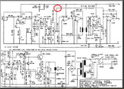
so i decided, as i gotta go with a reverb-in-a-bag kinda 9″ tank, i’m putting insulated rca’s in the bottom of the chassis for the reverb send and return, and if i’m going THAT far, i may as well add an fx loop to the sucker. now, i could just do simple switching jacks where i circled in red and likely be fine, but then i remembered the paramix circuit from here at good ‘ole guitarpcb. it appears it would work perfectly for a lot of functions i could seriously use…now, this little crappy amp has the identical power supply to the 30 watt one. the only real diff is the speaker load apparently. its supposed to see 16r, i’m running it at 8, i’ve run it at 4, no problem. it’s freeking LOU….not quiet. it has analog reverb. win-win.
i’ll never use the headphone output, and the line out can be moved. this opens up two more holes in the front of the amp. that will be for the extra pot for the blend control, not sure yet if i’m gonna add the dry pot or just leave it up. obviously, it’s probably worth adding.
but this will let me use a series loop for say, a volume pedal and the parallel loop for my echoplex or whatever.
am i nuts? yeah, pro’lly. so…. what, me worry?so… any thoughts or suggestions would be appreciated before i undertake this stupidi….madness.
i’m planning on using switching jacks in both loops, insulated ones, for the series and parallel loops.
i’ve got a +/- 15 v power supply i could run this at, but not really sure which way to adjust the resistors with this to run at that higher voltage, or if i should just tap a 9v regulator off the + rail to feed just this circuit. it seems like it would work tho to convert the paramix to a dual rail power supply that’s higher tho, as it should increase the headroom quite a bit and it seems like 4.5v of swing either way probably can’t handle the output of the preamp.
the caps i’m not worried about too much, but reccomendations for the resistors to get me in the ballpark would be awesome, as i am an idiot 10 toed monkey with a breadboard and too much time.or am i just wasting my (and your) time?
thanks peeps
PjP
February 12, 2022 at 5:01 pm #23115AnonymousInactiveand i have no problem cutting traces and adding jumpers… lol
February 12, 2022 at 6:56 pm #23116AnonymousGuestHey Jimi!
Sadly, I thought about converting the Paramix to a dual rail supply but realized that it probably won’t work. The existing board uses the ground plane as the bottom rail for the power supply. The reference ground is created by the resistors in the supply which form the Vb at 1/2 of the 9V rail. If you changed the GROUND to a -15V rail, all of the points that connect to the ground plane will become -15V. That means the chassis that connects to the IN/OUT jacks will become hot with -15V. All Vb points will become the reference ground.
Now if you insulate the jacks and board, you might get this to work. The TL074 chip can certainly handle the voltage. Let me know if you can do this. I always like the way you think out of the box!
February 13, 2022 at 2:07 pm #23128AnonymousInactivehola brother ray!
i was looking at it, thinking along those lines… what if i made the ground plane -15v, and used the half supply voltage as a “virtual ground”? i could disconnect the actual “ground points” that way, lift them and use jumpers to re-connect stuff. maybe its a pipe dream…
but then i was thinking too, just running it at 9v with a regulator off the positive rail would work, as its gonna be parallel anyways… i don’t need the insert jacks or any of the switching stuff, i could just jumper it then and use it as a parallel fx loop to blend in echoes etc. i don’t NEED to trick it all out necessarily, i could get by with just the send and return. if i ditch the headphone jack, i could add a pot right there for the blend level. i think this could work.
originally, i was gonna do the buff and blend circuit, but i realized that may result in phasing issues, and i don’t wanna have to add a bunch of daughterboards to it… so the paramix circuit SHOULD be about perfect. so i’m gonna build it up maybe today, and have a little experiment. i mean, worst case, i will just have to lay it out on vero and hack my own circuit, but i have faith this will be able to be adapted. i’m always up for a challenge, especially for insane ideas like this one 😉
thanks for the headsup and support bro… stay tuned!!
jimi
February 13, 2022 at 2:30 pm #23129AnonymousGuestCan’t wait to see your results. Take a break and watch the big game then heat up your solder iron!
February 13, 2022 at 3:08 pm #23130AnonymousInactive<hr />
hahahhah yeah, big game? i’d rather poke my eardrums with a knitting needle.
i’ll be in my dungeon having a good time instead 😉
February 13, 2022 at 7:59 pm #23140AnonymousInactiveso, so far…. i got the board built. not doing the series loop, or the kill switch. gonna try it at 15v. instead of using normal pots, i’m using a dual 100k for the dry/wet as a mix/blend control and see if it flies. stay tuned… may be a couple days, awaiting parts. so i don’t wanna commit to anything til i get to try it un-catestrophically 😉
February 14, 2022 at 12:32 am #23145AnonymousInactive‘kay, so looking at the schematic when i had one of them eureka moments.
this is a quad opamp. so that means i can take pin 11 of the jelly bean and point it straight up, plug the rest in a socket. run the + rail to pin 4, the – rail to the upended pin 11. the chip will run on +/- 15v, and the rest can remain the same as near as i can see. the half voltage is still gonna be in the middle, so the whole circuit should still work, in theory, anyways. worst case… magick smoke time, start again 8)
also decided to just go with the one knob in the back. the dry drive is a 100k trimmer (p1), i made r5 22k instead of 12k to get a tiny bit more gain in case something needs it. this will be a set and forget, anyways. no need to add a full size pot.
i combined the dry and wet levels into one stacked pot, wired as a panning control kinda….. i used a 100k dual stacked pot. my dislogic at the time was that since this is gonna be wired into the amp as a parallel loop, i’m really gonna just want to make it either drier or wetter. i expect i may have to tack a 47k resistor on each side of the pot to keep the volume up, gonna take a little playing with. half way up on the level should be an equalish mix of wet and dry signal. the wet signal is wired with its pin 1 to ground, the dry with its pin 3. so it will just let ya balance between the source and effect, hopefully. maybe i had too many s’kooby snacks? entirely possible.
used insulated switching jacks and ran a jumper between the unswitched hots, so if nothing’s plugged in it will just pass signal thru, plug in, some effects, and then it passes thru the effect as normal. ez breezy.too zonked tonite to wire up the 5 connections to see if it will work. hopefully, tomorrow. stay tuned…
by all means, if ya think i’m gonna summon some strange druidic demons or blow up something, tell me, pink, go get another cup of coffee…ahem… but i can’t see any reason why it won’t work. it will run the one chip in this circuit at the same voltage as the chips in the amp. i say dam the torpedoes, full speed onward… tomorrow… after a nap…
February 14, 2022 at 5:54 pm #23159AnonymousInactiveahem!!!
huzzah’s all around…. sumbeeotch works. had to make a couple mods… but it works, and not only does it work, it works GREAT.
holy cajones.
what i did was simple. pulled pin 11 up straight, plugged the tl084 into its socket. pin 11 got wired directly to the -15v rail in the amp, the +15v rail went to where the 9v was supposed to be, the half voltage tho changed remained half voltage for vb, the chip didn’t care how it got converted. everything’s effectively iso’d with caps… so it was an easy hack.
i shorted pins 2 and 3 of the dry signal together. so its full up. the wet signal i made a simple b10k, which worked perfect. i tried using a dual b100k with it wired as a “blend” … ie it would turn the dry down as you turned the wet up, and the wet down as the dry came up. it worked…. but really dismally. in the middle of the pot rotation, more than half of it in fact, it was less than unity and didn’t really justify itself. i tried raising up to a b500k pot, and it was worse, so went down to 10, which worked out about perfect.
i made the dry gain a 100k trimmer, as i figured it would likely be a set and forget kinda dealio. turns out it can also be used to drive the heck out of the amp as another gain stage… i made r5 22k instead of 12k, expecting it would be marginally louder, holy cow. i got the pot off. 😉so this necessitated raising the gain via r8, increased to 220k from 100k stock. you can turn the wet up just barely noticeably louder than unity that way.
jumpered switch 2.
the phase switch has problems with the 47u filter cap. i was a dummy and left it in, it made the amp get unstable and a cap start pop pop pop pop pop popping, the only electro i used was the 47, so i cut it out. problem solved. i DID leave the 4.7u but that’s an mcc. i may add one to the other rail, or may just cut it out completely.i did also add a strap from the non-switched tip connections on the insulated jacks i used, so when nothing’s plugged in, the signal passes thru normally like it was still hardwired.
i may add a relay and a switch and make a “blow” function where i can by pass that trim pot being turned all the way down… then boom instant lead boost via that presently unused gain stage. its THAT sick, yes, and worthy of consideration as i go thru this thing tricking it out.
the io/ii jacks are jumpered.
anyways, video or it never happened. using my d’lay with the tails mod i did in a video a while ago
works mint.no idea how the hell to get the video to display 😉
February 15, 2022 at 2:06 pm #23179Big OParticipantJimi, your posts are the greatest! Always give me a laugh or two. You just inject a lot of humor into the text. And I admit that I don’t fully understand a lot of the technical stuff so I am of little to no help unfortunately. I contemplating changing my major to EE but never made it there.
February 15, 2022 at 2:48 pm #23180AnonymousGuestNicely done, Jimi! A clever mod to make that TL074 run on a dual supply. BTW, it is rated for a + or – 18VDC supply.
February 15, 2022 at 3:00 pm #23182AnonymousInactivehahah thanks big o, its all about using everything for comedy. 😉
wilkie, good to know! it worked out great, i think i may add one to my 30 watt 1×12 combo too, but with both loop options. more room in the chassis!
after i did this vid, i socked it all down. still awaiting reverb parts and speaker, but here’s a couple pics of it where i left off last nite.
its a cool hack for this and similar amps, it really adds a bit to the versatility and works great in this circumstance.
just remember to run the fx in this kind of loop 100% wet or phasing may become an issue, but hey, for what i needed to do, the guitarpcb paramix worked out perfectly. the whole reason i originally bought it was actually to add an fx loop to a chipamp deal i was toying with making but never got to. peteytwofingers turned me on to the little chines “class d” amplifier boards a couple years ago, he uses them to build battery powered yet high output amps for when him and his fam do “remote jams” out in the woods.
i love this little pcb. one more use for this swiss army knife of circuits!February 20, 2022 at 3:24 pm #23235AnonymousInactivewon’t let me update this thread… weird!
oh well… all the info is here:
https://www.diystompboxes.com/smfforum/index.php?topic=128767.0
February 20, 2022 at 3:25 pm #23236AnonymousInactivehey gang,
so recently i picked up a blown up marshall 12 watt reverb combo. when i say blown up? i mean LITERALLY.
this model had a tankless reverb deal mounted right to the amp pcb,
and one of the 3 springs broke somehow.
when it did, it literally took out the amp inside…. the spring melted into about 16 parts!!!
never seen that much destruction in this way before..
most of the amp was destroyed, and much of it had been disassembled by the seller, who gave up on it.
i was like….. hmmm…. 80 bux? i’ll give it a shot.
so he sent me the amp, minus the speaker, and when it arrived i was like…. Damn, dude, this is more f’d up than
a soup sandwich.why do i post this shit on aron’s stompbox forum? cuz for all intents, this amp is a damn stompbox with an amp attached… google up the marshall 3005 vero on tagboard. great circuit.
sounds like a marshall in the box, well, cuz it IS a marshall in the box…. but i digress… big surprise, right?there’s a thread on guitarpcb i started about it… here:
ultimately, i had to replace all the electros in the circuit, all the diodes but the 9.1v one, the power transistors, the diode bridge, the power transformer as well… one side of the secondary, that fed the + voltage rail was literally gone, all this stuff got smoked when that spring broke.
so i went on a hunt, found all the parts, and got the amp working again.
the proper transformer for these, btw, is a hammond 166j28 28vac center tapped transformer. its the proper one for the 3005 and the 5005 as well, but in the 5005, due to the reverb, it clocks differently, so it needs to have two holes drilled in the chassis to make it fit, cuz otherwise the amp hanger is in the way.
hook it up the same as the original, bam.made my own diode bridge with 4 1n4001’s. easy breezy. now i had b+ voltage again, a solid 15.1v on positive and negative rails.
i got the proper power transistors, in multiples, and installed them.removed all three 1458’s and replaced with sockets. was hoping they survived, but all three were damaged, so i replaced them with modern 1458’s. now the amp would fire. psyched.
the reverb was still dead tho, so i went on a hunt to find another.
this link has a pdf you want to save, that will de-mystify what a pain in the ass it is trying to figure out
what reverb tank you actually need:http://www.electricalfun.com/workbenchfun/reverb_tank.pdf
turned out, i had a stack of old reverbs around so i kept trying one til i found one that would work… i got a dcr on each end of 170r, so i looked for something similar.
what was left of the original tank was showing a dcr of 34r/220r. i tried contacting marshall, but they have no records from these suckers nearly 40 years out.
so i went hunting… i could order exactly what i needed from belton…. if i wanted to buy a shit load of them. nope. just need one.
so i used the reverb guide pdf thingy to see what my options were, and came up with the following codes… meaningless? nope… all them numbers/letters stand for stuff… see the pdf
bsn3ba31a
8db2c1d
8bb3d1a
belton
bs3fb31b
8fb3d1b
so i went on antique to try and find a suitable replacement. ended up finding something close enough for rock n roll in a mod tank, 9″ small one, three springs, long decay
save ya some hassle… this is the correct pan for this, as well as the 5210 30 watt combo:
https://www.tubesandmore.com/products/reverb-tank-mod-8fb3c1b-long-decay-3-spring
so i got the tank, and some iso’d rca jacks, and added the reverb back to the circuit. boom!!! it lived again!
used one of them new-fangled celestion g10-30’s in it, which worked out just right, mainly cuz i am CHEAP. it was like, 35 with free shipping from victor litz musix, aka “the woodwind and the brasswind”.
February 20, 2022 at 3:25 pm #23237AnonymousInactiveso now the amp was working… as an extra added bonus, since the power supply and amp are identical in this amp and the 30 watters <and almost identical to the 50 watters>
i [s]stole[/s] jm fahey’s post on the solid state amps forum and put in an 8 ohm speaker instead of 16. this bumped it up to 30 watts from the “12” it was. boom.so now i had a clean running amp that had killer verb and was loud as hell… perfect for my old guy back. whole amp weighs in about 20 lbs now. love it.
but i was looking at it and going… ya know, if i take the signal after the master volume, and break it, and add a pair of switching jacks, i can add an fx loop for my echoplex…
[url=https://postimg.cc/tZp7bfGJ][img]https://i.postimg.cc/tZp7bfGJ/marshall-12-watt-reverb-mod.jpg[/img][/url]
where the red is circled was where i was intending to break the circuit… thinking that way, i could just be easy about it….
but then i was thinking, shit, what if it becomes a phasing issue or something?that’s when i remembered barry’s paramix, which i had bought several boards for years ago in hopes of using with a chipamp dealio like petey twofinger’s live amps i was messing with… and realized, with the gain controls and phase switch, would be perfect for my needs:
[url=https://postimg.cc/njWzmLQj][img]https://i.postimg.cc/njWzmLQj/paramix.jpg[/img][/url]
so i took it an populated it, and made a couple mods… i just jumpered the series fx loop part, cuz i didn’t need it in this amp, and was kinda wondering if i didn’t already have too many holes in it.
in for a dollar, in for a dime.also jumpered the dry level of the mixer part so it was full up. i tried using a dual 100k pot to sweep the wet and dry, but in the middle it was dismal, so ended up just jumpering the dry signal half to be on full, and made the wet signal pot b10k instead, which gave a nice and useful sweep to the wet mix pot. perfect.
i kept the phase switch, and used a tl082 cuz it was the first quad i pulled out of the semiconductor drawer.looking at it, i pondered how the hell i was gonna power it. wilkie on barry’s forum said the jellybean was good up to 18v and i was like, cool, so how am i gonna do this?
that was the eureka moment… i had the diodes/caps for the bipolar supply right there… so i simply ran a ground from one of the 22uf cap’s ground side to the ground on the paramix, and the 15v+ to the 9v in on the board.
then i pulled out the 082, lifted pin 11 so it wasn’t in the socket, and connected the 15v- directly to the pin.
BOOM! now i had the same voltage swing as the rest of the preamp! worked out mint, tho i DID have to remove the 47u electro, which caused problems with the phasing switch… if ya flicked the switch, you’d get a pop…..pop….pop….pop…. kinda thing.. i realized that was the only electro on the board, so i just snipped it off. popping ended.c9 in the marshall, a 220nF cap was the easiest insert point, so i grafted in the daughterboard there… i cut one side of the cap, the side to the master volume, and then soldered leads to the two ends of that cap’s cut lead, and hooked in the fx loop. boom.
tested it… now i had a functioning fx loop in the amp. drilled a couple holes, and mounted the phase switch, send and return jacks <iso’d, important!!! use wah wah style 1/4″ jacks> and was like, cool! so now i got reverb and a useable fx loop in this little beast, and have doubled the output power, to boot. and the “overall level” of the daughterboard, i made a 100k trimmer. i keep it all the way down, tho it can be used to juice the amp more at the expense of a bit of reverb or delay or whatever.
February 20, 2022 at 3:29 pm #23239AnonymousInactivei made r5 22k instead of 12k, thinking it would be handy to have a bit of a “bump” for volume. this meant i had to raise r8 on the daughterboard up to 220k from the stock 100k to keep the “wet” level up a bit more.
now that trimmer? you could hook it up to bypass it, or switch to the trimmer setting for a lead “boost” if ya wanted to. i’ve toyed with it, but haven’t bit yet. you could use a high z cable and a simple dpdt or 3pdt footswitch, but its gonna be a long run and may cause signal degradation or popping or noise from rfi etc. so if i DID do it <which i still may> i’d likely use a 15v relay hidden in the amp to keep the noise down, but that’s another story and this is already too long.
so now it was just about perfect. the reverb i stuffed in a bag, under the speaker like in a fender, and used regular rca cables to hook it up. so the amp works now, the reverb is restored, and it has a functioning effects loop while looking bone stock.
btw, the phase switch is important and useful! when i first tried my 2399 echo, if the switch is down, and the echo is out of phase, it doesn’t work well… but up, in phase, it’s perfect…. so its worth keeping.
so finally i was like…. ya know….
what would make this sucker PERFECTER would be if i added a 9v output jack to the back to power my cheezy echo pedal with…. so i drilled one more hole, and mounted a 2.1mm power jack <iso’d, of course…. anything like this, you want to isolate it from ground so you don’t get hum…. “ground” in this case is the neutral potential between the +/- rails>so first thing i thought was…. hey! i can add a l78l09 right to the pads for the electro i’d snipped off, run a couple wires, and boom! 9v, right?
well… it worked… sorta. its amusing to hear what happens to a 2399 when starved for current. the echoes go all over the place at random pitches.. kinda cool. but not really…xin loi! <sorry, but not really>
February 20, 2022 at 3:30 pm #23240AnonymousInactivethe l78l05 was supposed to be good for 100ma current, but… no. when the guitar was barely on, it would work… but once ya hit the amp hard, and it sagged, the echo would freak out.
so i go to myself, self, yer a dumbass… of COURSE it ain’t working right, you used a dang regulator with no capacitor support… so i made another daughterboard, this time with a 100r resistor in line as a ” choke”, a 10u cap on the input and a 2.2u cap on the reg output. much better… until the amp sagged…. echoes all over. i thought it may be the resistor, so i bypassed it. better, but ,,,
not really, same shit it was doing. echoes all over the place.so i said… nope.
and i went instead with a simpler idea… a 9.1v zener diode between ground and the + rail to drop the 6 volts or so from the 15, a 10uf cap, and a 2.2nf “snubber”….also between ground and +.
boom! bingo! now i got a solid 9.45 vdc output on the back of the amp to run a couple pedals with. done! now it all works great.
here’s a couple pics:
-
AuthorPosts


- You must be logged in to reply to this topic.