
Your Source for DIY Pedal PCBs and NostalgiTone! › GuitarPCB Forum › GuitarPCB Build Support › Muff’n V4 Troubleshooting (solved)
- This topic has 19 replies, 4 voices, and was last updated 10 months, 2 weeks ago by
 Billy.

-
AuthorPosts
-
December 4, 2025 at 6:17 am #37966Port Side CrisParticipant
Hey everybody! New to the forum and new to pedal building. I was wondering if there were any voltage specs/check points available for the Muff’n V4. I built it up and it sounds likevthe worst overdrive you ever heard! About half the volume, little to no gain. I socketed the transistors and verified they were in proper orientation. I also made sure J1-J4 are jumpered. I was hoping to get some voltage specs and where to check for voltage or even some resistance specs and check points. I also did make sure I have 9.4 volts going to the main PCB and the daughter board. I did check voltage to the transistors as well; 7-8 volts to each. Is that too high maybe? Any help or input at all would be great! Thank you all!
December 4, 2025 at 8:25 am #37970BillyModeratorWelcome
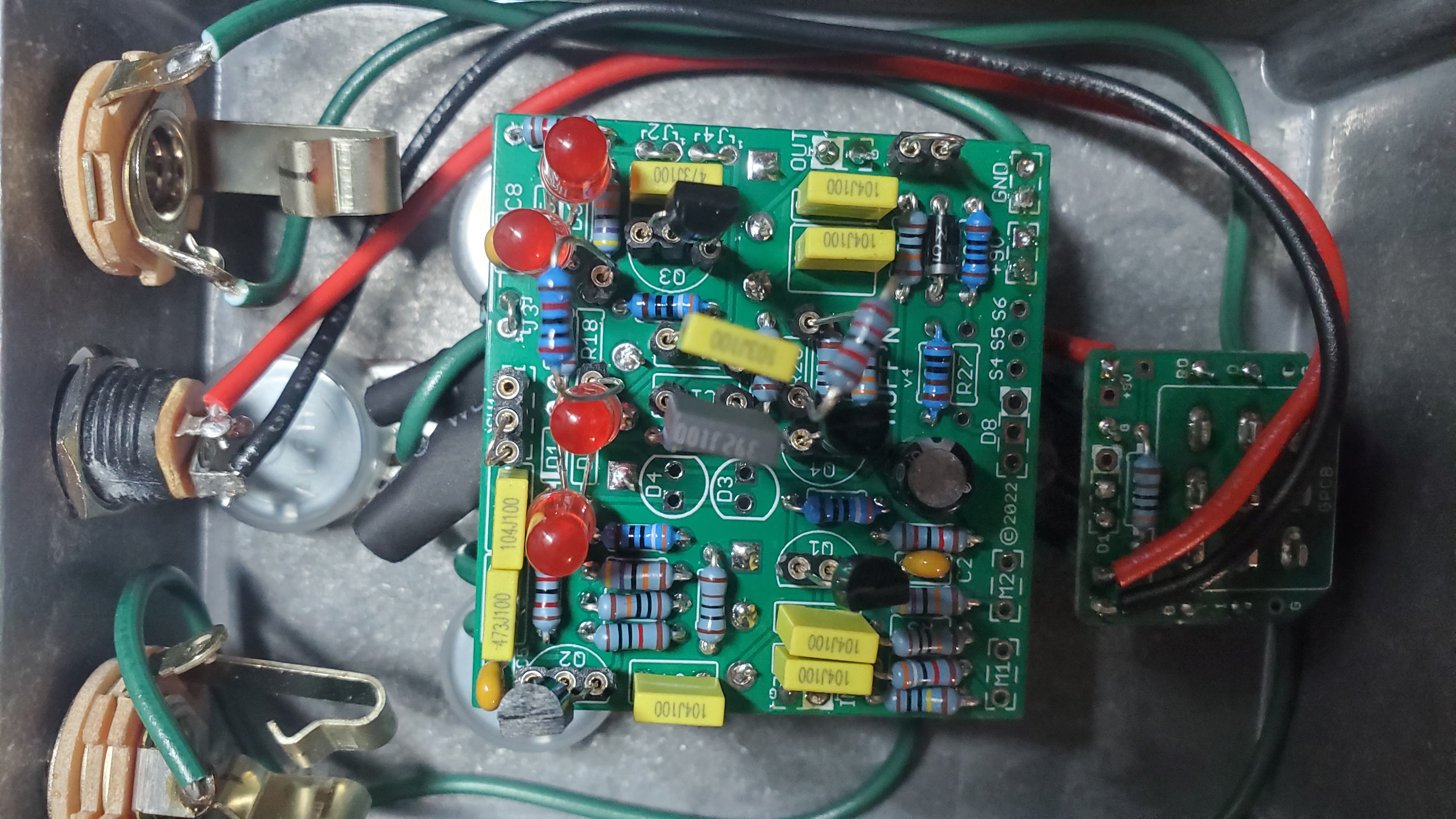
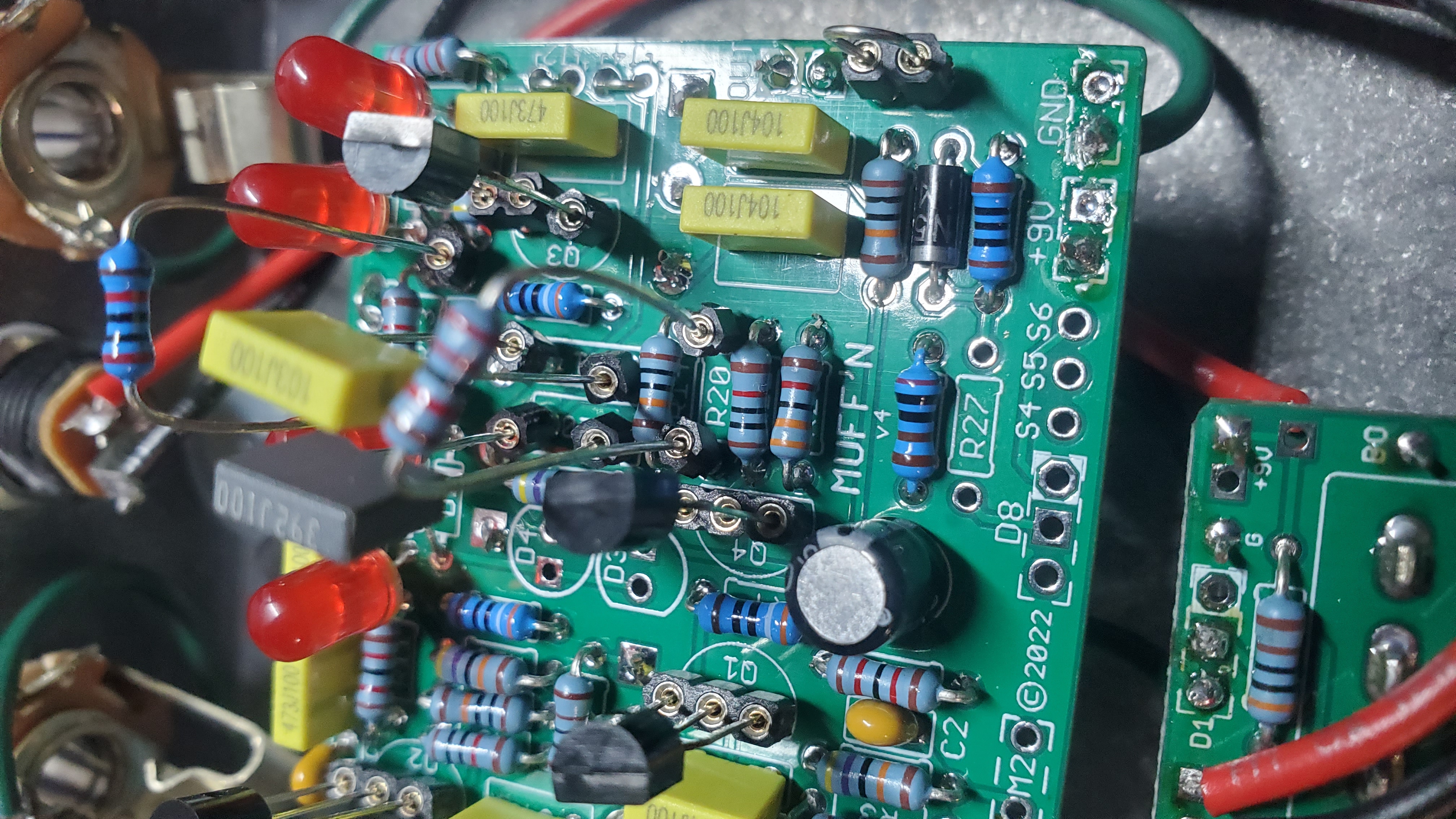
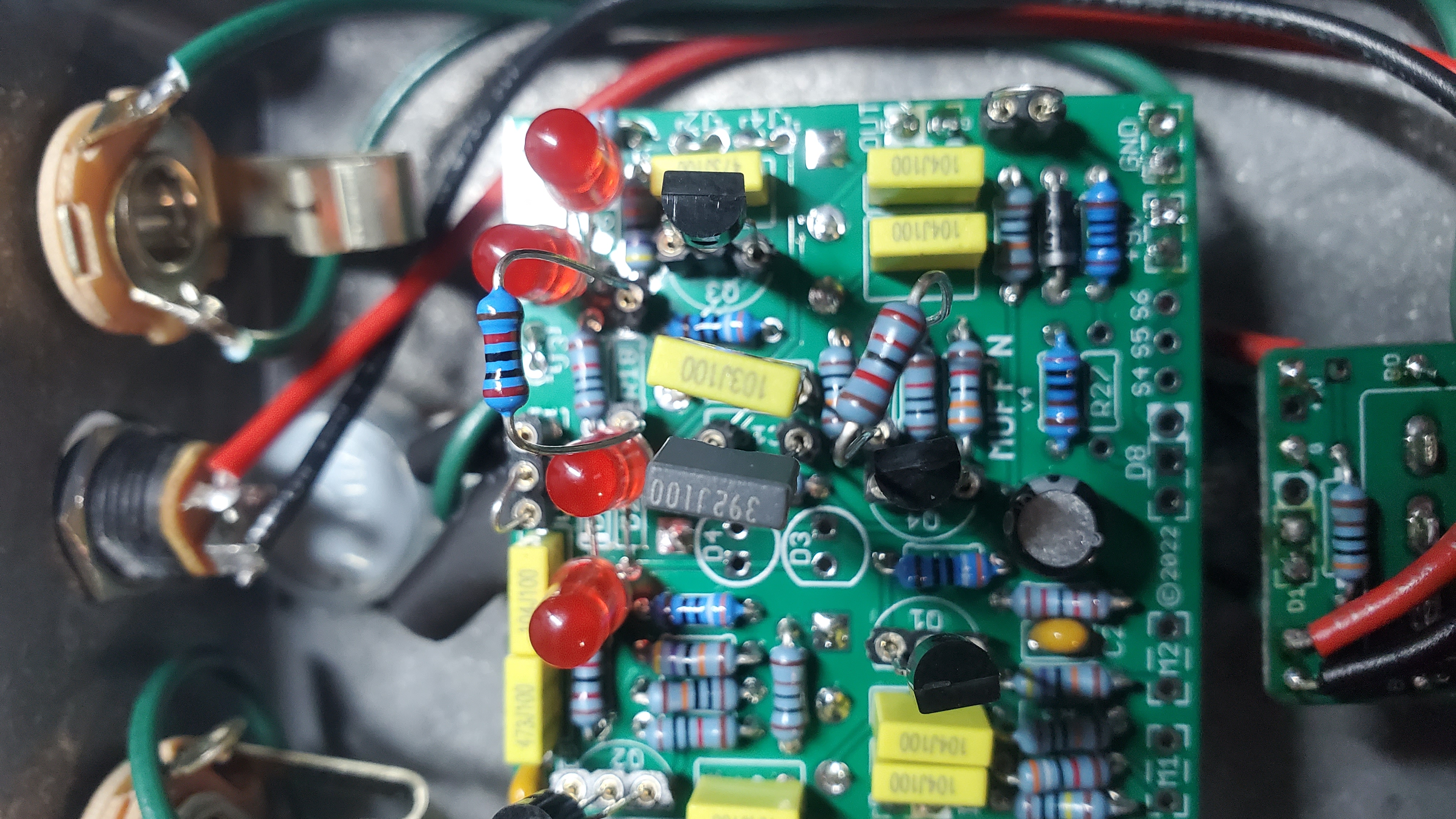
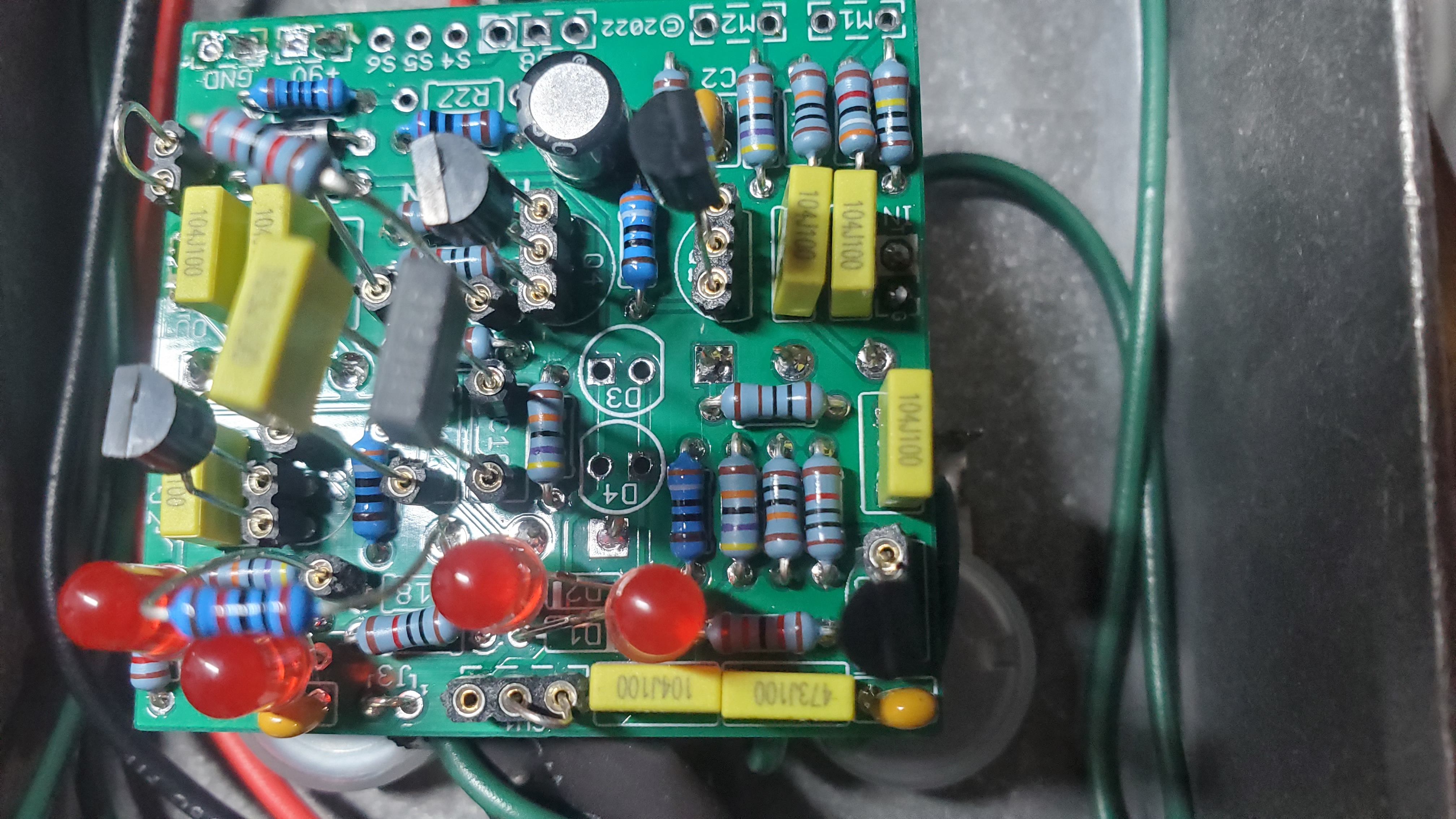
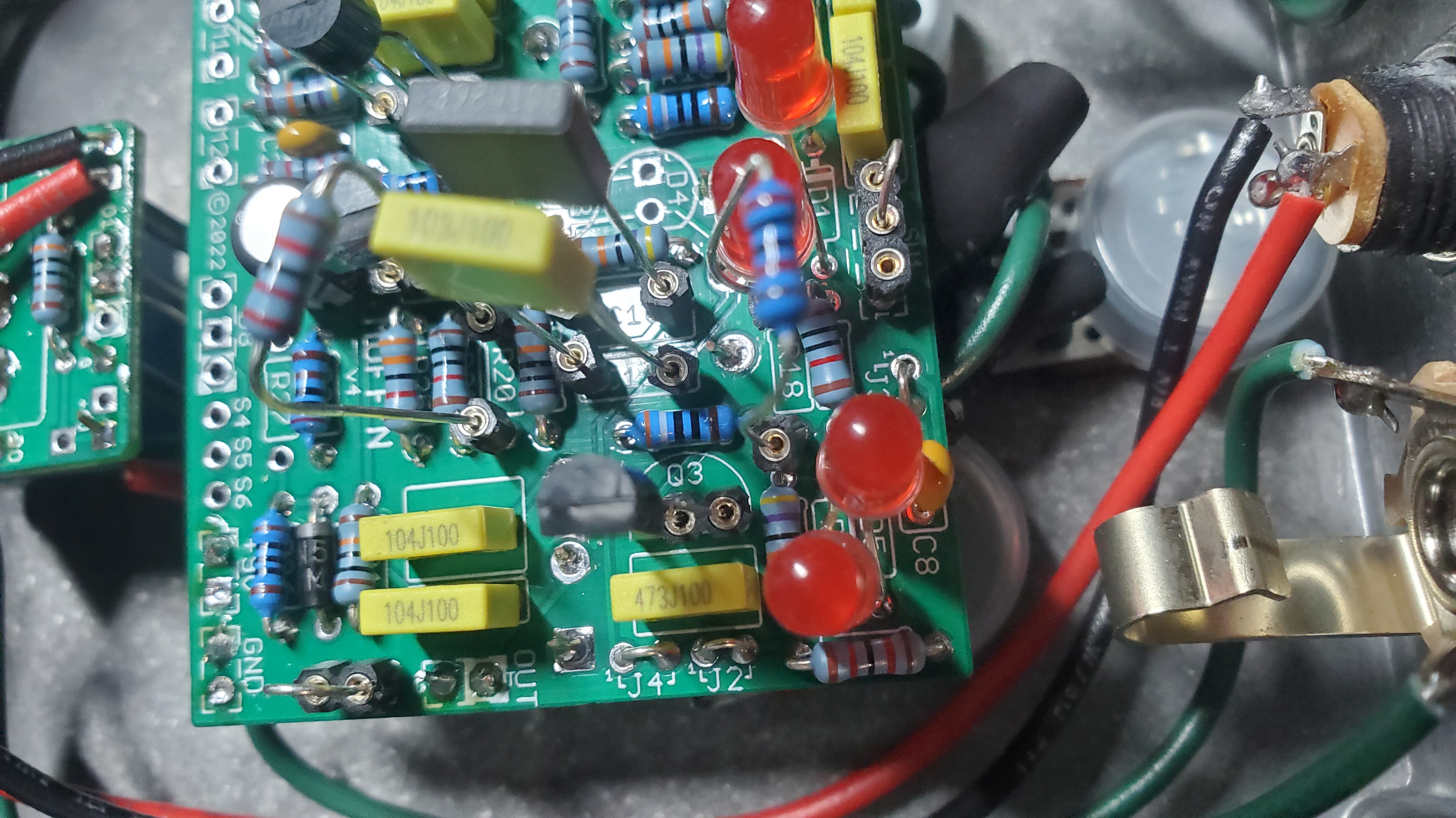
Post some nice clear in focus images of the component side of the pcb so that all component values and orientation can be clearly seen
With most Muff variants the transistor voltages will be more or less the same give or take a few mV
These voltages are from a general guitar gadgets muff
Voltage in 8.8v
Q1 – C 3.9, B 0.6, E 0.03
Q2 and 3 – C 3.8, B 0.6, E 0.03
Q4 – C 4, B 2.5, E 1.8
December 4, 2025 at 5:52 pm #37974Port Side CrisParticipantDecember 4, 2025 at 5:53 pm #37975Port Side CrisParticipantDecember 4, 2025 at 5:53 pm #37976Port Side CrisParticipantDecember 4, 2025 at 5:54 pm #37977Port Side CrisParticipantDecember 4, 2025 at 5:54 pm #37978Port Side CrisParticipantDecember 4, 2025 at 5:57 pm #37979Port Side CrisParticipantThanks for the info! And I apologize in advance for the multiple photo posts. I couldn’t figure out how to get it all on one post. You will noticed I opted to use LEDs for the clipping diodes and I also decided to socket R18, R20, C10, and C11 referring to the schematic so that I could tweak around with the tone circuit in the future. Just for fun! I also found that I had to socket the SW1 pads and put a jumper in the correct position to get voltage to my clipping diodes. Hope this helps you help me lol. Thanks again!
December 4, 2025 at 7:36 pm #37980AnonymousInactiveWhich variant did you use that omits D3 & D4?
December 5, 2025 at 4:35 am #37984Port Side CrisParticipantI used the green Russian variant. Going off of the build doc and schematic it seemed D3 and D4 were optional and I opted not to use mod 6 in the build doc.
December 5, 2025 at 8:07 am #37986PlaysforfunModeratorSometimes the thinner legs of some components can have a fiddly or less than perfect connection with those sockets. That may at times give puzzling results. It’s happened to me several times with transistors, for example, while firing up a build after using cheap sockets. Worth a second look if you haven’t already.
December 5, 2025 at 8:32 am #37987BillyModeratorIf you haven’t already try swapping your SW1 jumper to the other outer pad I can’t see how it connects on the build doc pcb image but it’s worth a try it may be you’ve jumpered it in the D3 / 4 position which would obviously cause an open circuit with D3 and 4 being empty
You could do a quick continuity check to make sure D1 anode or D2 cathode connects to one side of either C5, R8 or R10
*edit build doc mod 6 says jumper SW1 pads 1 and 2 you’ve jumpered 2 and 3 so try moving your jumper middle to the other outer pad hopefully that’ll be it and you don’t have any other problems
December 5, 2025 at 9:45 am #37988Port Side CrisParticipantThanks for the suggestions everyone! Yea unfortunately I have tried all of those things initially with no luck 😕 I did find that with the jumper installed where it currently is, there is now no voltage to D3 and D4 and I have voltage to D1 and D2. Originally I did not so that’s when I switched the jumper over. Still the same result unfortunately. I will have to recheck my voltages to my transistors and compare them with what was posted because my memory tells me they are way off.
December 5, 2025 at 5:57 pm #37992Port Side CrisParticipantSo after checking and writing down my voltages to the transistors I have gathered the following with 9.39 volts going in;
Q1: E=7.98 volts B=0.59 volts C=0.03 volts
Q2: E=7.98 volts B=0.59 volts C=0.03 volts
Q3: E=7.59 volts B=0.58 volts C=0.03 volts
Q4: E=8.23 volts B=0.76 volts C=0.2 volts
These seem to be a little high compared to what was posted earlier. Anybody got any input? Thank you!
December 5, 2025 at 9:50 pm #37995PlaysforfunModeratorHas it been said which transistors you are using and whether they are situated correctly? My voltages are very similar to Billy’s.
December 6, 2025 at 8:01 am #37997Port Side CrisParticipantOk I messed this all up. I looked up the datasheet for the BC549C which is what I am using and the emitter voltages and collector voltages should be swapped in my readings. I apologize about that. So once more I have 9.38 volts going in;
Q1: C=7.98 volts B=0.59 volts E=0.03 volts
Q2: C=7.98 volts B=0.59 volts E=0.03 volts
Q3: C=7.59 volts B=0.58 volts E=0.03 volts
Q4: C=8.23 volts B=0.76 volts E=0.2 volts
I believe I verified that they are in fact oriented correctly because I tried flipping them the other way and found no sound comes out at all. I also rechecked continuity between D1 anode and D2 cathode to one side of C5, R8, and R10 and have verified good continuity. I also checked my voltages at my diodes ans have the following;
D1: Anode=0.59 Cathode=0
D2: Anode=0 Cathode=0.59
D3/D4 no voltage and not populated since mod 6 is omitted
D5: Anode=0 Cathode=0.58
D6: Anode=0.58 Cathode=0
December 6, 2025 at 8:12 am #37998Port Side CrisParticipantWell now I’m confused because I just googled another datasheet for the BC549C and found that my pinout was correct? I guess it would help if I knew for sure who the manufacturer was. I’m not sure. What do you folks think? It would make sense that it’s oriented properly if sound at least passes through vs not at all if oriented the other way correct? I’m just at a loss here. My apologies.
-
AuthorPosts




- You must be logged in to reply to this topic.