Your Source for DIY Pedal PCBs and NostalgiTone! › GuitarPCB Forum › GuitarPCB Build Support › DLAyV3 nothing
- This topic has 15 replies, 3 voices, and was last updated 2 years, 10 months ago by
 Scott Bourgeois.
-
AuthorPosts
-
May 21, 2023 at 12:29 pm #28680Scott BourgeoisParticipant
I have built about 20 pedals with a 90% success rate. I’m building 3 D’Lay v3 pedals. 2 are back ups. I get voltage to the Bi-Led Anode and the Transistor gets warm but no signal in bipass or on and no Led in on or off. I have voltage on all of the resistors and caps on the non GND sides
I have checked for cold joints and continuity throughout. I’m still trying to perfect my soldering.
Wired the footswitch directly as in the build documents with the switch oriented in the right way.
Anything else I can try?
May 21, 2023 at 1:21 pm #28684Scott BourgeoisParticipantMay 21, 2023 at 6:15 pm #28686BarryKeymasterNo signal in bypass means the off-board wiring (In – Outs) is incorrect, faulty foot switch, or faulty jacks.
In other words, you are not getting a signal to pass from the In jack through the 3PDT to the Out jack with the main board entirely bypassed.
There is no way to trace the off-board wiring with the photos provided. (no jacks in photos)
May 21, 2023 at 8:06 pm #28689Scott BourgeoisParticipantThanks BArry, I have oriented the PCB upside down because I wanted the time control on the left,Level in the middle Repeats on the right so it’s a bit difficult to show the jacks. They are wired as shown in the build document In,Gnd, and Out,Gnd to tip/sleeve. Ignore the other switch and PCB as they are a future tap tempo mod. I recently built the Mastadon Fuzz that has the same foot switch wiring and it works as it should.
May 24, 2023 at 2:55 am #28728Scott BourgeoisParticipantI discovered that my output jack was shorting out against the copper shielding. I now have a bypass signal but no effect or bi color LED when on or off. Transistor gets warm.
May 24, 2023 at 3:01 pm #28733BarryKeymasterYou have an additional short somewhere.
I would remove the circuit board from the enclosure entirely and test it by itself (no additional mod boards) You may have to replace the transistor or LED if they were damaged.
It is too hard to see but also make sure your audio wire from the 3PDT is going to the Jack TIP and not RING. I would not use stereo jacks unless I were using a battery. Also not sure why there are loose nuts stuck between the jack and copper in the photo. That is a short ready-to-happen after inserting the guitar cable.
July 25, 2023 at 12:29 am #29315Scott BourgeoisParticipantHi Barry, D”layV3 still not working. I have checked all resistors, caps, diodes, Replaced transistor and swapped both ICs. I have voltage at the Bi LED
I have clean signal in bypass. Engaged I get an extremely quiet distorted echoed signal when engaged. The Bi LED has been tested good but does not light up.
Bare bones photos attached
July 25, 2023 at 6:29 pm #29318BarryKeymasterProvide voltages on both ICs and the voltage regulator in a sorted list below.
 July 25, 2023 at 8:59 pm #29320BillyModerator
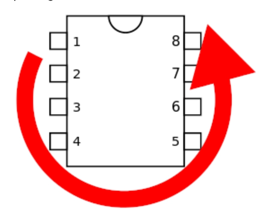
Your PT2399 is the wrong way around notch should be at the bottom
I’m assuming you’ve oriented it that way because the socket notch looks to be at the top too obviously the socket being upside down doesn’t matter
Where did you get your bi colour LED? is it common anode
July 25, 2023 at 11:24 pm #29321Scott BourgeoisParticipantHi Billy, The socket notch is in backwards I now have the PT2399 with the notch facing the correct way now. My Bi colour LED came from a local store Has a common anode and I tested it with a 3 volt battery pack. Still nothing
July 25, 2023 at 11:29 pm #29322Scott BourgeoisParticipant<p class=”p1″>3.91 on the TL072</p>
<p class=”p1″>1.7 on the PT2399</p>
<p class=”p1″>4.991 on the L78L05</p>
<p class=”p1″>2.6V at Diode 1n4001</p>
<p class=”p1″>293mV at Diode 1n5817</p>July 26, 2023 at 10:01 am #29323BillyModeratorYou’d need to post voltages for each pin on the ICs
Like this
PT2399
1. 5v
2. 2.5v
3 0v
4 0v
Etc for all pins of each IC using the pin numbering orientation in Barry’s diagram
If your output for the L78L05 is 4.99v that’s OK
Did you try swapping the PT2399 in case it’s damaged I think with incorrect orientation you may have caused a dead short with ground pins connecting to power
Depending on how long you had it powered this way it may have caused damage
July 26, 2023 at 12:41 pm #29324Scott BourgeoisParticipantWith a 9.25v Power Supply
PT2399
1=4.9v
2=2.4v
3=0v
4=0v
5=4.4v
6=2.4v
7=0.7v
8=0.7v
9 thru 16 = 2.4v
TL072
1=4.4v
2=4.4v
3=4.3v
4=0
5=4.4v
6=4.4v
7=4.4
8=8.9v
1n4001= 4.9v
1n5817= 9.0v
78L05 between 1and 2 Out/GND 4.9v, 2 and 3 GND Input 8.9v, 1 and 3 3.98
Bi Colour common cathode LED =8.9v
July 26, 2023 at 3:21 pm #29326BillyModeratorThose voltages all look good, pin 5 is a bit high on the PT2399 but afaik it’s not used
Do you have and know how to use an audio probe
All your component values and orientation that I can see look correct
You get bypass that indicates the jacks and bypass side of the 3PDT are OK
Try reflowing the solder joints on the 3PDT lugs going to the pcb in and out pads reflow on the 3PDT lugs and solder pads they look like they could potentially be dry
Your voltages as I say look good so it’s hopefully just something like a dry solder joint stopping audio getting through the circuit in effects mode
July 28, 2023 at 2:40 pm #29342BarryKeymasterAn Audio Probe is a fantastic tool to easily locate a problem area
July 30, 2023 at 12:28 am #29356Scott BourgeoisParticipantThanks for the tip. I cobbled one together with a radio, a mini guitar amp some alligator clips and a probe. Seems to work well.
-
AuthorPosts


- You must be logged in to reply to this topic.