@port-side-cris
Forum Replies Created
-
AuthorPosts
-
December 7, 2025 at 10:32 am #38006
 Port Side CrisParticipant
Welp good news! I cut the excess legs of the socketted components and flipped the orientation of the transistors like Billy said and I finally have a successful working muff’n. Thank you folks for all the assistance! I knew it had to be something silly. I apologize for the ignorance on here but I guess I learned a couple of things here.
December 6, 2025 at 8:12 am #37998Port Side CrisParticipantWell now I’m confused because I just googled another datasheet for the BC549C and found that my pinout was correct? I guess it would help if I knew for sure who the manufacturer was. I’m not sure. What do you folks think? It would make sense that it’s oriented properly if sound at least passes through vs not at all if oriented the other way correct? I’m just at a loss here. My apologies.
December 6, 2025 at 8:01 am #37997Port Side CrisParticipantOk I messed this all up. I looked up the datasheet for the BC549C which is what I am using and the emitter voltages and collector voltages should be swapped in my readings. I apologize about that. So once more I have 9.38 volts going in;
Q1: C=7.98 volts B=0.59 volts E=0.03 volts
Q2: C=7.98 volts B=0.59 volts E=0.03 volts
Q3: C=7.59 volts B=0.58 volts E=0.03 volts
Q4: C=8.23 volts B=0.76 volts E=0.2 volts
I believe I verified that they are in fact oriented correctly because I tried flipping them the other way and found no sound comes out at all. I also rechecked continuity between D1 anode and D2 cathode to one side of C5, R8, and R10 and have verified good continuity. I also checked my voltages at my diodes ans have the following;
D1: Anode=0.59 Cathode=0
D2: Anode=0 Cathode=0.59
D3/D4 no voltage and not populated since mod 6 is omitted
D5: Anode=0 Cathode=0.58
D6: Anode=0.58 Cathode=0
December 5, 2025 at 5:57 pm #37992Port Side CrisParticipantSo after checking and writing down my voltages to the transistors I have gathered the following with 9.39 volts going in;
Q1: E=7.98 volts B=0.59 volts C=0.03 volts
Q2: E=7.98 volts B=0.59 volts C=0.03 volts
Q3: E=7.59 volts B=0.58 volts C=0.03 volts
Q4: E=8.23 volts B=0.76 volts C=0.2 volts
These seem to be a little high compared to what was posted earlier. Anybody got any input? Thank you!
December 5, 2025 at 9:45 am #37988Port Side CrisParticipantThanks for the suggestions everyone! Yea unfortunately I have tried all of those things initially with no luck 😕 I did find that with the jumper installed where it currently is, there is now no voltage to D3 and D4 and I have voltage to D1 and D2. Originally I did not so that’s when I switched the jumper over. Still the same result unfortunately. I will have to recheck my voltages to my transistors and compare them with what was posted because my memory tells me they are way off.
December 5, 2025 at 4:35 am #37984Port Side CrisParticipantI used the green Russian variant. Going off of the build doc and schematic it seemed D3 and D4 were optional and I opted not to use mod 6 in the build doc.
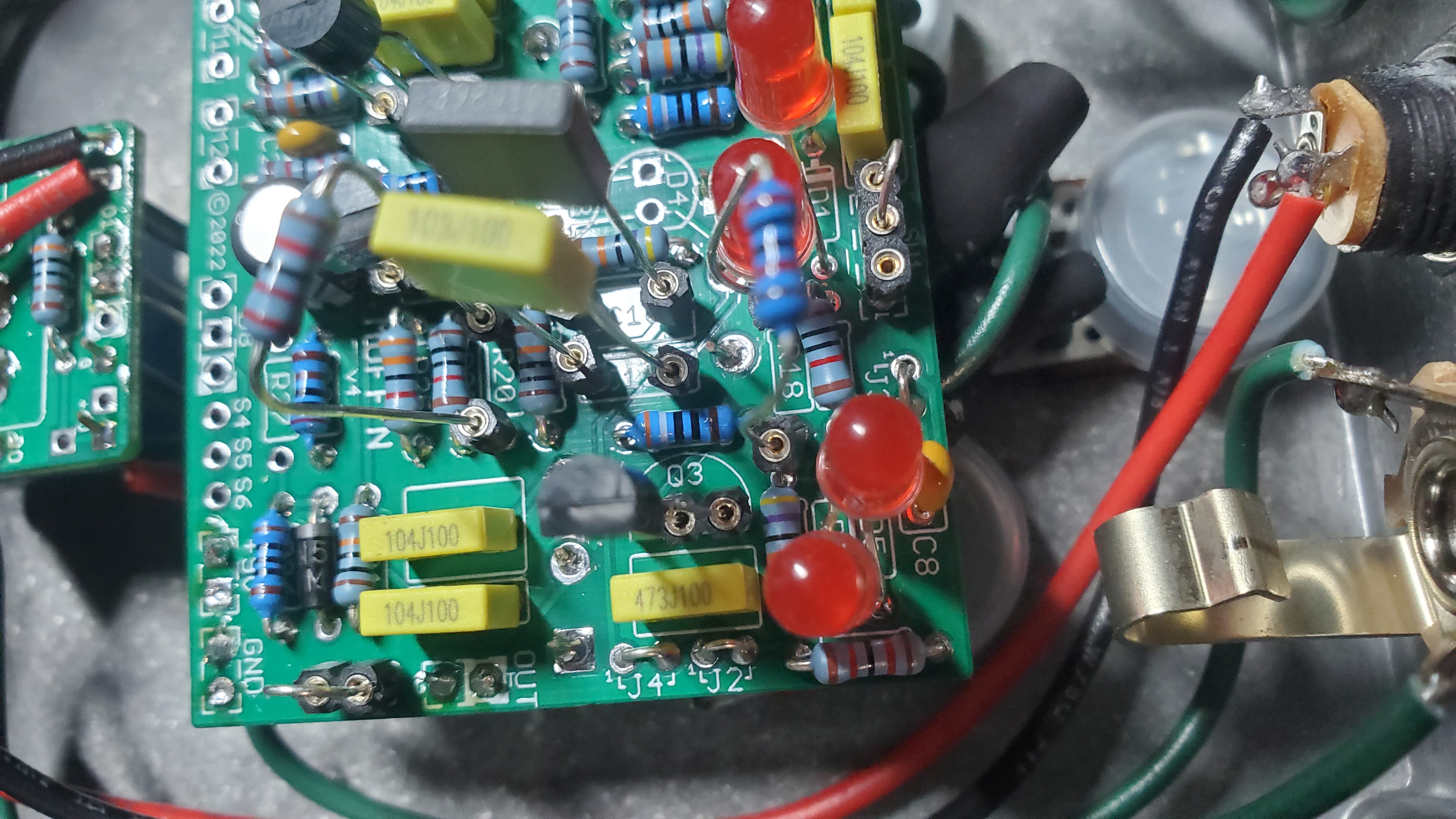
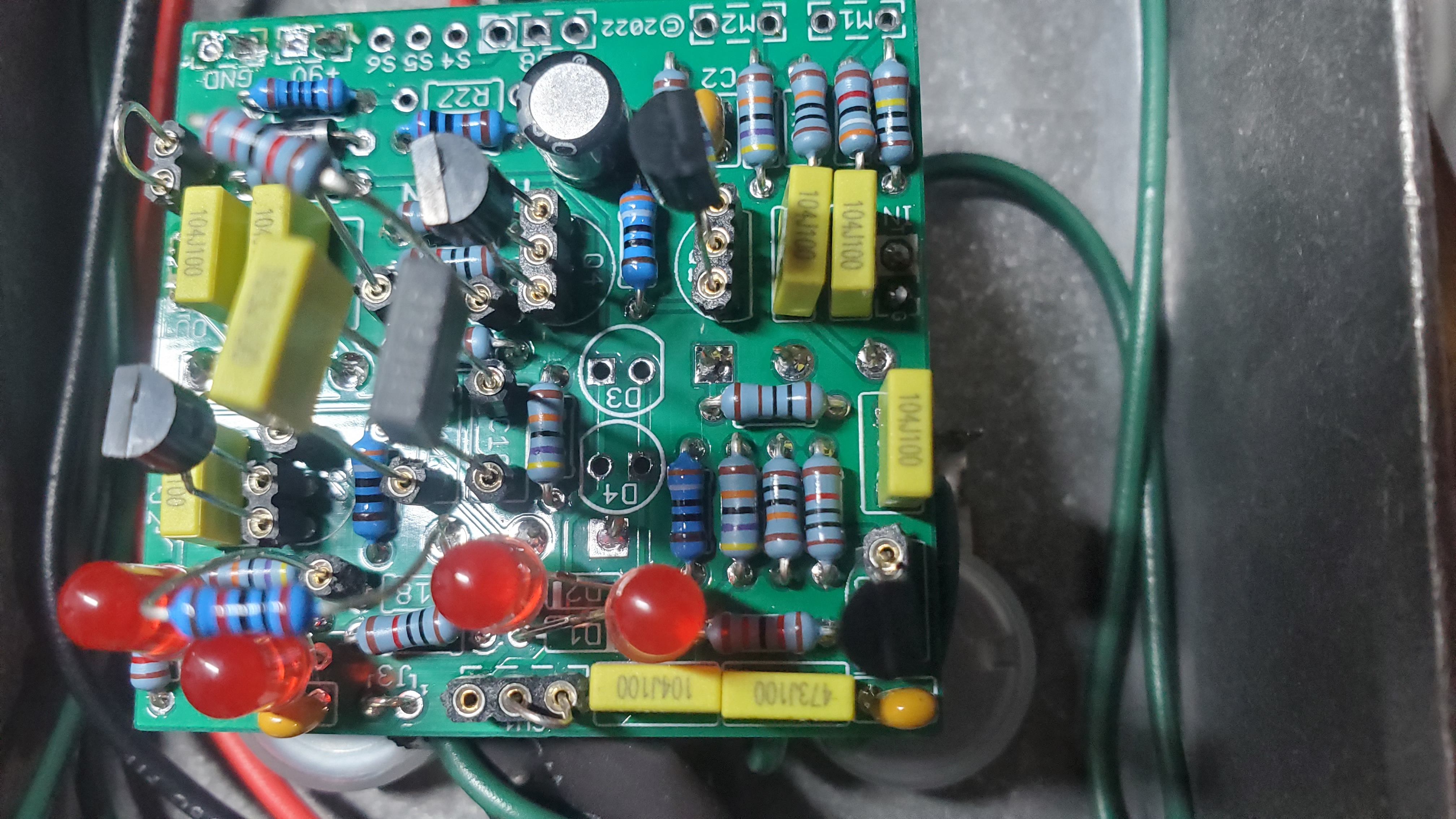
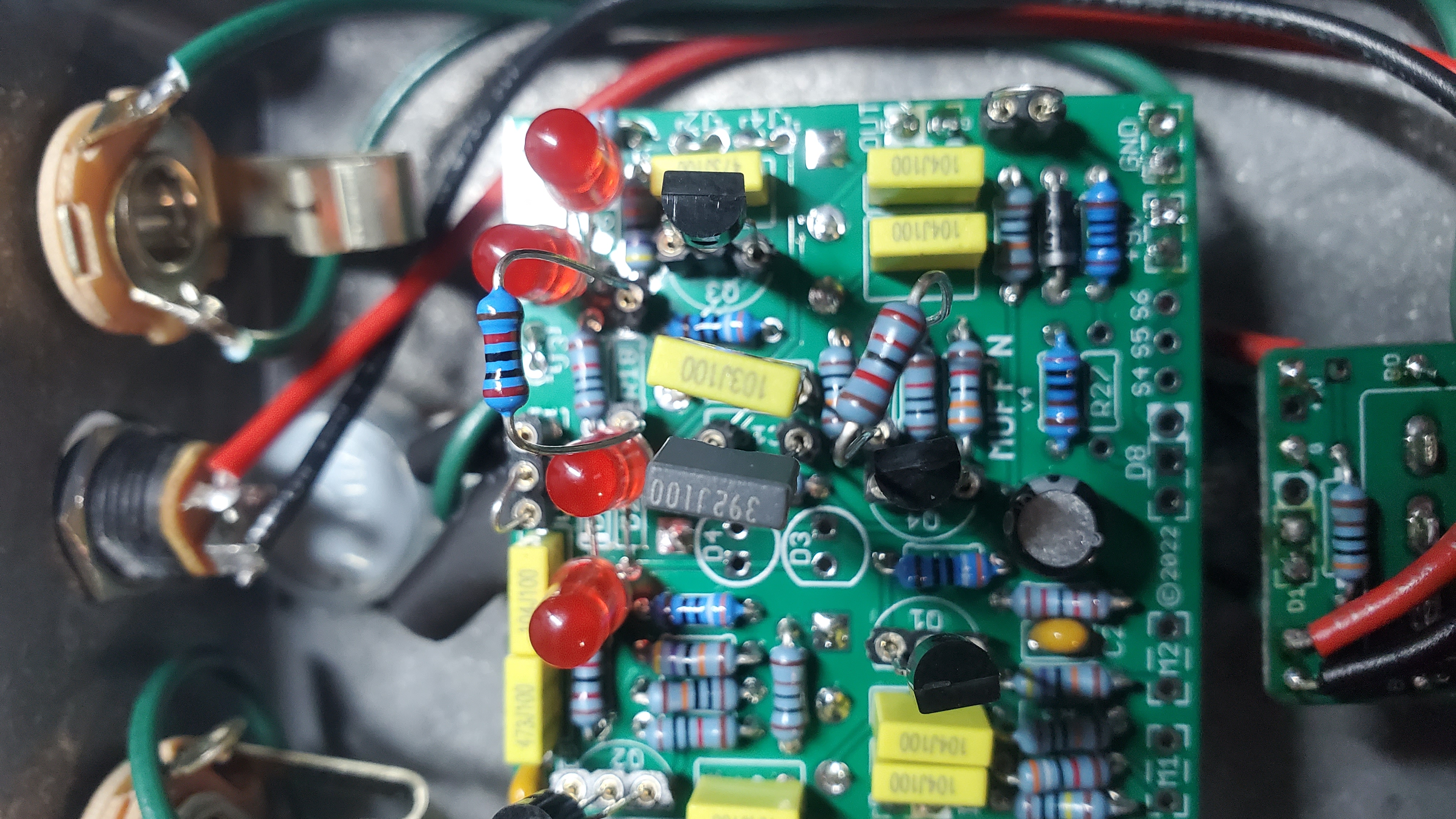
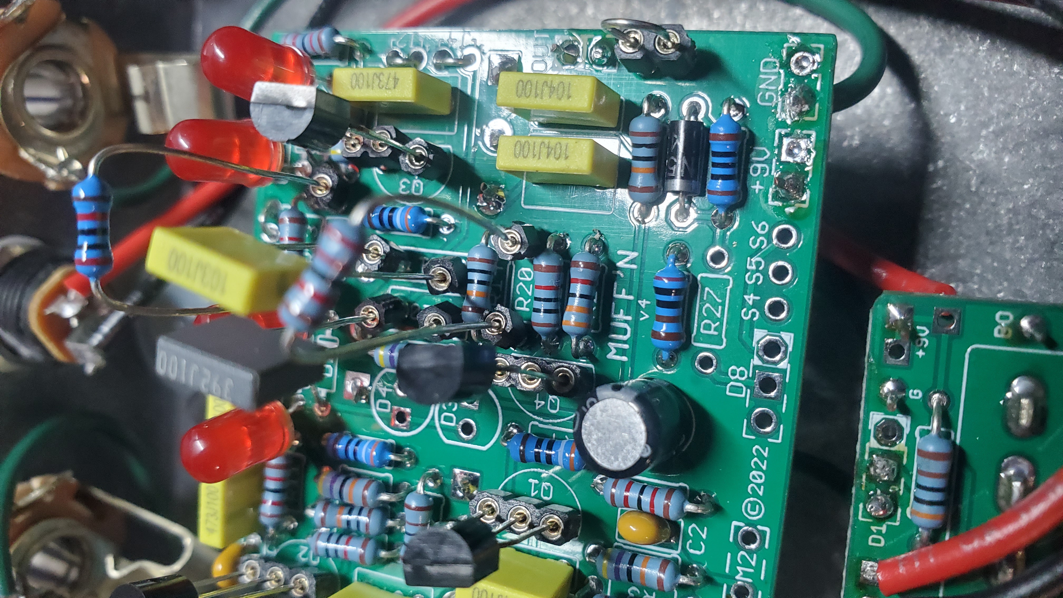
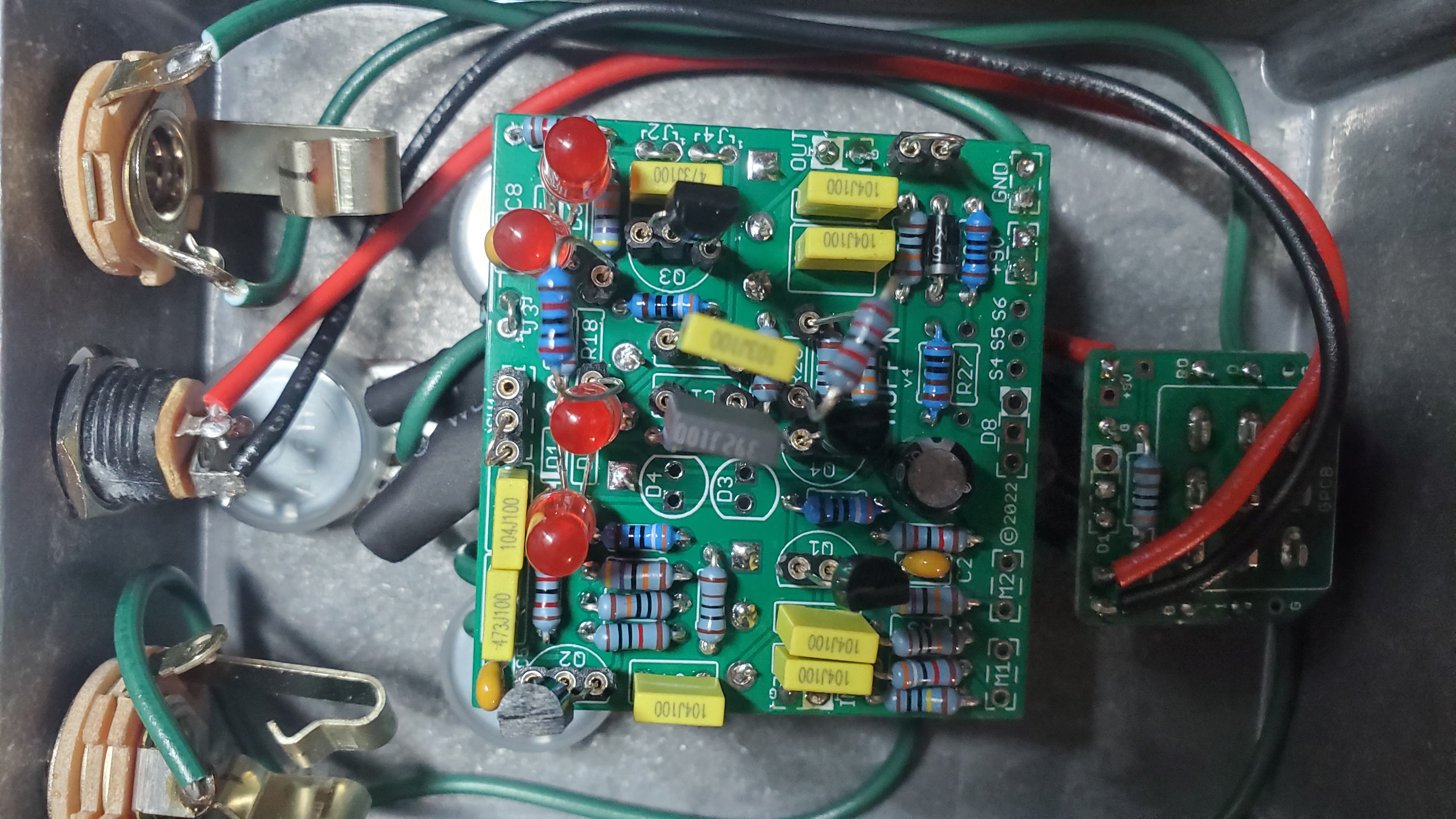
December 4, 2025 at 5:57 pm #37979Port Side CrisParticipantThanks for the info! And I apologize in advance for the multiple photo posts. I couldn’t figure out how to get it all on one post. You will noticed I opted to use LEDs for the clipping diodes and I also decided to socket R18, R20, C10, and C11 referring to the schematic so that I could tweak around with the tone circuit in the future. Just for fun! I also found that I had to socket the SW1 pads and put a jumper in the correct position to get voltage to my clipping diodes. Hope this helps you help me lol. Thanks again!
December 4, 2025 at 5:54 pm #37978Port Side CrisParticipantDecember 4, 2025 at 5:54 pm #37977Port Side CrisParticipantDecember 4, 2025 at 5:53 pm #37976Port Side CrisParticipantDecember 4, 2025 at 5:53 pm #37975Port Side CrisParticipantDecember 4, 2025 at 5:52 pm #37974Port Side CrisParticipant -
AuthorPosts