@benlec
Forum Replies Created
-
AuthorPosts
-
January 24, 2026 at 11:54 am #38240
 Ben JiParticipant
is this what you call oscillate ? this is Lug 6 after i replaced IC3 with a more trustworthy supplier. did not test the pedal yet but i can tell you i never had this on this Lug
January 24, 2026 at 11:32 am #38239Ben JiParticipant<span style=”-webkit-tap-highlight-color: rgba(0, 0, 0, 0);”>g2 is very well grounded i have verified it is connected to the jack and from the jack i go to another ground.</span>
with no IC3 we have
L2: 2,5/2,3v
L3: 3,7/3,8v
L6: 2,8v
L7: 8,9vall other Lugs are 0v
January 17, 2026 at 9:41 am #38225Ben JiParticipanti reflew around C8 , R22/24/25 + IC3 socket. no progress
January 5, 2026 at 11:55 am #38171Ben JiParticipantOK i’ll try to reflow a few of these around and let you know how it goes. thanks a lot
January 2, 2026 at 3:38 am #38152Ben JiParticipanti agree.. i need to source proper ones. this pedal will not work with this PNP. thanks!
January 1, 2026 at 1:54 pm #38150Ben JiParticipant- Pin6 clearly does not oscillate
- I tried reflew C8 solder joints
What do you think about the JFET values i gave ? does it look good to you?
December 30, 2025 at 4:03 pm #38143Ben JiParticipantthe speed pot affects voltage on Pin2 up or down a bit if i turn it clockwise or counterclockwise but does not oscillate ‘alone”. Pin6 voltage does not change when i turn the speed pot
December 30, 2025 at 3:57 pm #38142Ben JiParticipantRegarding Q5 2N4125, i have tested a few from the bag i have (x10) i didn’t touch the one on the board.
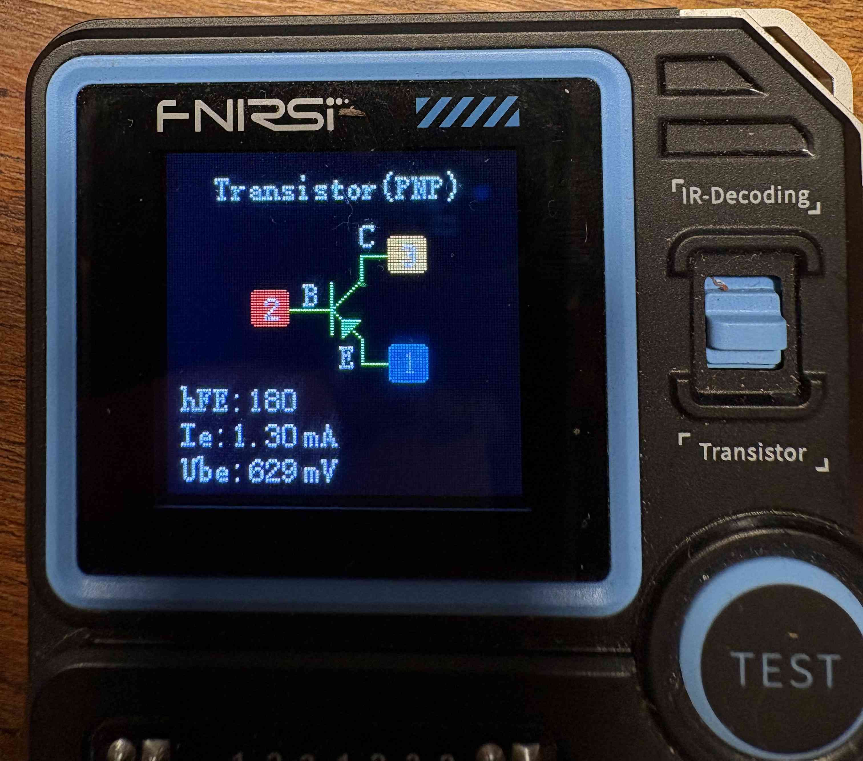
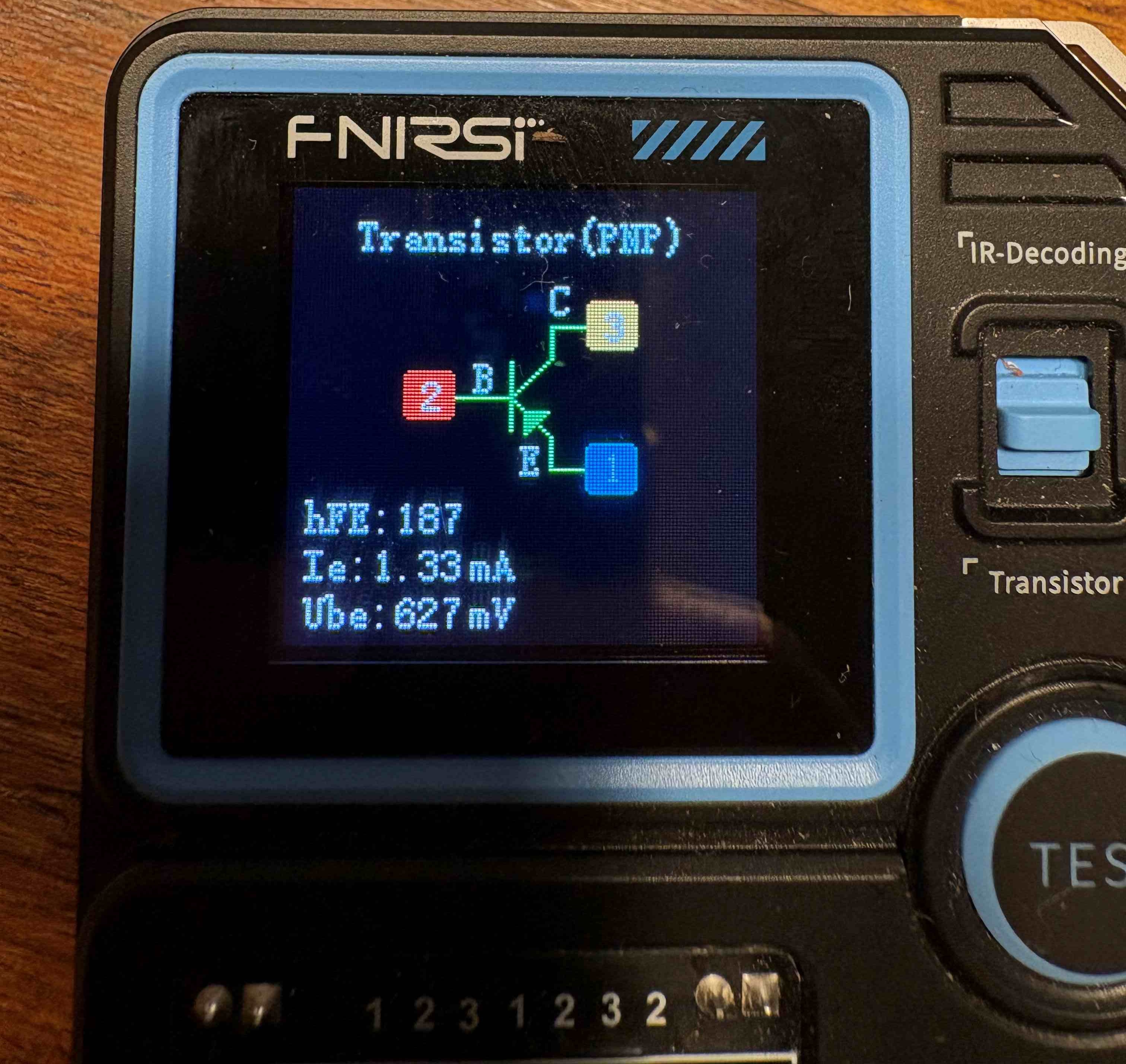
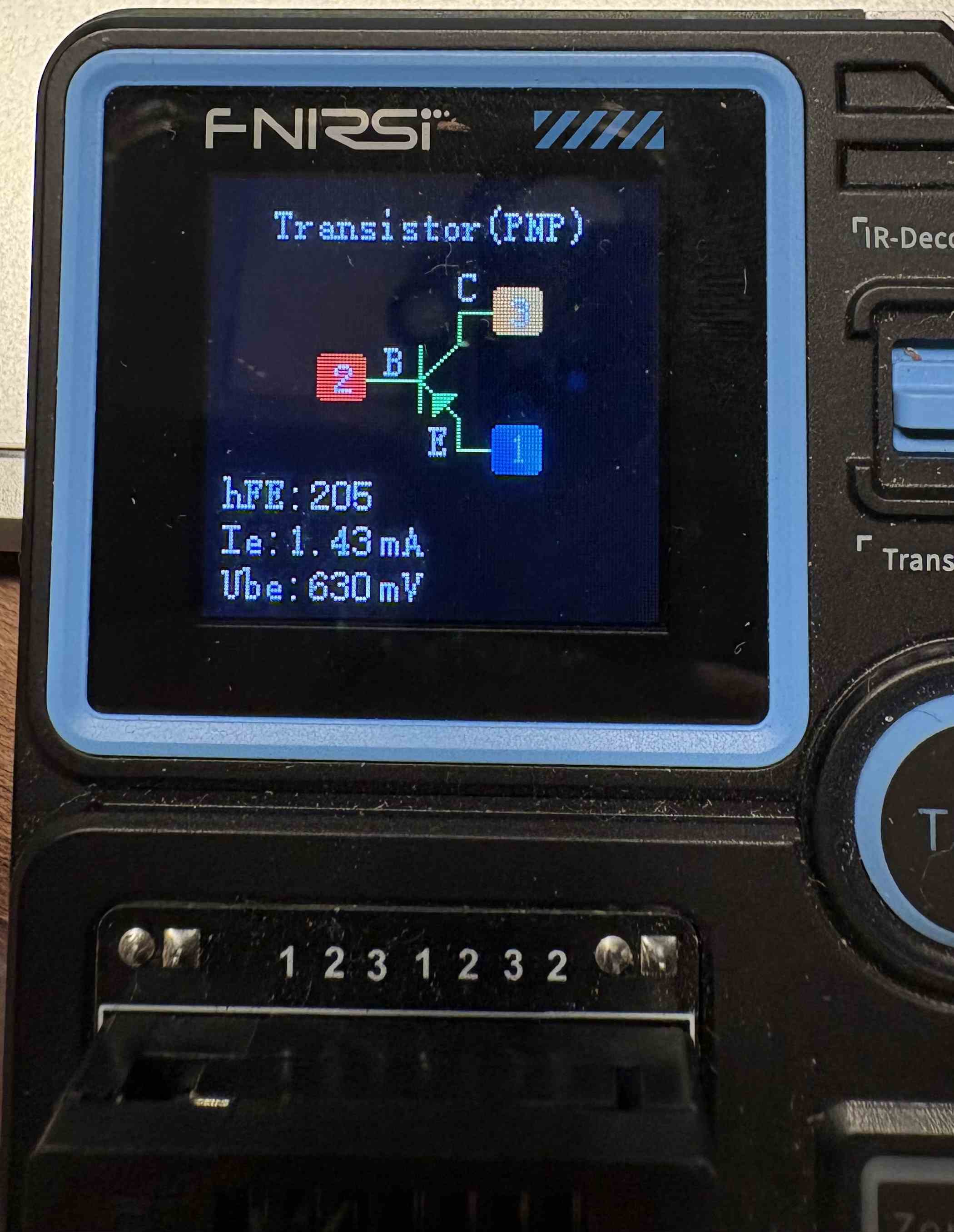
I used the FNIRSI LCR-P1 which provides:
– DC current gain -> hfe,
– base-emitter voltage drop -> Ube,
– Ic/Ie, collector-emit-ter reverse cutoff current -> IceHere are the values for 3 FET i took from this bag (new), i’m not sure these value matches the datasheet. What do you think? It is difficult to say because there are so many values.
December 30, 2025 at 3:23 pm #38139Ben JiParticipantI understand and agree about what you are saying about replacing components. I would not got into detail about the why i did this but now i understand why i should not.
R23 down side : 2,13V
R23 top side : 2,83V
Q5 is 2N4125will bring more complete answer later
December 29, 2025 at 3:51 am #38130Ben JiParticipantOh I am so sorry about that, yes i know how to read this numbering in theory but clearly i got distracted 🙁 i read column by column, so after translation to correct reading method this makes:
- IC3/P6 voltage is 8,94v and does not oscillate (tested with classic multimeter)
- i have pushed harder the IC and had a few clicks showing they main not have been properly clicked
- R24 is 4,7k
- i just change R23 for a new one and R14 because i had some doubts
- ——————-
- IC3/P1: 6,68v
- IC3/P2: 2,14v (reading starts at a higher value then stabilize)
- IC3/P3: 3,89v
- IC3/P4: 0v
- IC3/P5: 0v
- IC3/P6: 2,83v (reading starts at a higher value then stabilize)
- IC3/P7: 8,95v
- IC3/P8: 7,92v
- —————-
- IC1/P1: 0v
- IC1/P2: 4,81v
- IC1/P3: 3,24v
- IC1/P4: 0v
- IC1/P5: 0v
- IC1/P6: 4,8v
- IC1/P7: 9,10v
- IC1/P8: 0v
- —————-
- Ic2/P1: 4,8v
- ic2/P2: 4,8v
- ic2/P3: 4,7v
- ic2/P4: 9,10v
- Ic2/P5: 4,7v
- ic2/P6: 4,8v
- ic2/P7: 4,8v
- ic2/p08: 4,8v
- ic2/p09: 4,8v
- ic2/p10: 4,7v
- ic2/p11: 0v
- ic2/p12: 4,7v
- ic2/p13: 4,8v
- ic2/p14: 4,8v
- —————–
- Q5 bottom pin ( on the board picture) : 4,8v
- Q5 middle: 4,23v
- Q5 top pin: 2,83v
- R23 top: 2,3v
December 28, 2025 at 7:29 am #38127Ben JiParticipantDecember 28, 2025 at 7:27 am #38126Ben JiParticipant- IC3/P6 voltage is 8,94v and does not oscillate (tested with classic multimeter)
- i have pushed harder the IC and had a few clicks showing they main not have been properly clicked
- R24 is 4,7k
- i just change R23 for a new one and R14 because i had some doubts
- check video for pot/lug2 test
- IC3/P1: 6,68v
- IC3/P2: 2,14v (reading starts at a higher value then stabilize)
- IC3/P3: 3,89v
- IC3/P4: 0v
- IC3/P5: 7,92v
- IC3/P6: 8,95v
- IC3/P7: 2,83v (reading starts at a higher value then stabilize)
- IC3/P8: 0v
- IC1/P1: 0v
- IC1/P2: 4,81v
- IC1/P3: 3,24v
- IC1/P4: 0v
- IC1/P5: 0v
- IC1/P6: 9,10v
- IC1/P7: 4,8v
- IC1/P8: 0v
- Ic2/P1: 4,8v
- ic2/P2: 4,8v
- ic2/P3: 4,7v
- ic2/P4: 9,10v
- Ic2/P5: 4,7v
- ic2/P6: 4,8v
- ic2/P7: 4,8v
- ic2/p8: 4,8v
- ic2/p9: 4,8v
- ic2/p10: 4,7v
- ic2/p11: 0v
- ic2/p12: 4,7v
- ic2/p13: 4,8v
- ic2/p14: 4,8v
- Q5 bottom pin ( on the board picture) : 4,8v
- Q5 middle: 4,23v
- Q5 top pin: 2,83v
- R23 top: 2,3v
December 27, 2025 at 1:56 pm #38122Ben JiParticipantalso don’t you think we are missing something more obvious? something pretty stupid i would have done?
December 27, 2025 at 1:54 pm #38121Ben JiParticipantthanksq again. so i do not have oscilloscope hence cannot tell you what is happening right now on IC3/P6. i can only tell you voltage is 8,8v. Also before posting here i worked on this with a friend way more skilled than me and he already identified that IC3/P6 did not oscillate using oscilloscope. we also tried various voltage with the trimmer without luck (very slowly) i tried again right now to test for each increment (trimmer is actually not that difficult to fine tune)
Additionnaly i have tried the voltage on speed pot lug 2: Voltage does change goes from.. 2.1v and goes up slowly then can go down. the logic of this variation is difficult to understand for me.
December 25, 2025 at 10:56 am #38118Ben JiParticipantI set them all at 2,08v i hope it is ok. They show all the same voltage. Same issue, sound is not modified. Does it hurt if a bit higher like 2,3v ?
December 23, 2025 at 2:15 pm #38113Ben JiParticipantDid you use the trimmer to set the jfet gate voltages to just over 2v
I guess you mean at #2 on IC3?
December 23, 2025 at 3:20 am #38109Ben JiParticipanti bought 2N5952 matched transistors from banzai music. You can see one of them here.
-
AuthorPosts