
Your Source for DIY Pedal PCBs and NostalgiTone! › GuitarPCB Forum › GuitarPCB Build Support › Problem with Sabotage build (solved)
- This topic has 11 replies, 3 voices, and was last updated 5 months, 1 week ago by
 Billy.

-
AuthorPosts
-
December 14, 2025 at 3:57 pm #38051dalangloisParticipant
Hello!
I’m on my second pedal build from a Pedal Parts & Kits kit with all the supplied components. The first one was the NostalgiTone Spring Reverb and it was a success. I’ve now assembled the Sabotage v2 kit (not 2.1), and I’m getting a sound that “sputters” and “farts out.” There’s tons of gain, but the controls do seem to affect what they’re supposed to. I’m also hearing an oscillation or a kind of warbling on certain notes.I’ve double-checked all the components to make sure nothing was installed incorrectly, and I’ve carefully inspected the board for possible shorts or open circuits, but I can’t find anything. Swapping the JFETs in their sockets does change the sound, but the issues remain. I have a bunch of J201s on hand, and I know they’re not supposed to bias correctly in this circuit, but in my case they seem to make the pedal almost usable, at least by ear.
What could I check to make sure the 2N5485s are working properly?
Thank you!
December 14, 2025 at 7:21 pm #38053BillyModeratorPost some nice clear in focus images of the component side of the pcb so that all component values and orientation can be clearly seen and offboard wiring traced
It does sound like a mis biased transistor what transistor are you using in the Q1 position
December 14, 2025 at 8:14 pm #38054dalangloisParticipantOutput jack was reverse wired hence the shrink tubing and color change. Q1 is a BC550.
December 14, 2025 at 9:49 pm #38055AnonymousInactiveC8 & C12 look to be reversed. Never mind … Just read the red amendment on the build document.December 14, 2025 at 9:57 pm #38056dalangloisParticipantHi! Thanks for having a look!
I read in Build doc for v2 specifically asks to reverse C8 and C12 from the silkscreen layout. Was corrected in v2.1.
<hr />
December 15, 2025 at 1:25 pm #38058BillyModeratorAll your components I can see look to be the correct value and orientation
What voltages do you get on all transistor pins Q1 EBC and Q2 to 6 DSG take voltages with the range pot fully clockwise
I’d suspect a mis biased transistor from your fault description
Fets as you’ll know are all over the place even from the same batch the fact it changes when you swap them around could indicate a biasing problem it could be anything from a poor solder joint on a biasing resistor to a transistor not fully secured in its socket
December 15, 2025 at 2:15 pm #38059dalangloisParticipantHi! Thank you for your time!
Here are the transistor voltages :
Q1 : 1.29V , 1,88V, 5,43V
Q2 : 8.19V , 5.82V , 3.9V
Q3 : 5.6V , 0.24V , 0V
Q4 : 8.18V , 4.14V, 0.5V
Q5 : 2.77V , 1.17V, 0V
Q6 : 8.18V , 4.3V , 3.7VDecember 15, 2025 at 11:51 pm #38062BillyModeratorQ1 looks OK that’s the treble boost / naga viper ish part
Q3 and 5 look off to me but unfortunately I don’t have the circuit on hand to check voltages
That’s assuming your readings are EBC Q1 and DSG pin order for Q2 to 6
I’ve probably confused that a bit Q1 pins top to bottom are EBC, Q2 to 6 top to bottom are GSD
Check C8 and 12 negative sides have continuity to ground
Are the fets 2N5485s
December 16, 2025 at 6:58 am #38064dalangloisParticipantHi again!
Yeah I made sure to write the readings in the order you asked, pinout for BC550 was the other way around of the FET, right to left vs left to right.
C8 and c12 negative sides indeed have continuity to ground.
FETs are 2N5485.I’ll try to get some replacements to try out (seems to be a good practice to have some on hand due to their inconsistency), while testing/replacing parts around Q3 and Q5. I’ll get around building an audio probe too, that could be useful!
December 16, 2025 at 7:34 am #38065BillyModeratorCheck the voltages you get with Q3 and 5 removed from their sockets to see if there’s any difference
I’ve just noticed Q4 gate looks low that should be similar to Q2 with your voltage divider R16 and 17 around half supply voltage less the 0.4v drop through D1
Check the voltage you get at the two voltage divider junctions R8 and 9 and R16 and 17
Try reflowing R18 solder joints the source of Q4 should be almost the same as Q5 drain you’ll notice Q2 source is almost the same as Q3 drain in what looks like a mu amp set up so even though we don’t know exact voltages we can see from the schematic they should be very similar
If R18 is difficult to get to with no power to the circuit check resistance between Q4 source and Q5 drain which should be around 1K or similar to the resistance between Q2 source and Q3 drain
Do you know if your meter has a 1M or 10M input impedance just so we know how accurate your readings are
Anybody that’s got the pedal if you could post transistor voltages that’d be great
December 17, 2025 at 11:44 pm #38080dalangloisParticipantHi!
I think I finally have it working properly! I tried to keep track of everything I did, but it may have been more than a single issue.
The Q4 socket contacts are definitely problematic. I probably got something stuck in there because the pins seem loose now. I ordered some replacements, but that was definitely part of the problem. I’m currently getting good-looking voltages, but I’m temporarily using Q4 with the pins slightly bent.
I also reflowed quite a few joints around R18-R19-C8-C11-Q5 and cleaned some gunk left on the PCB.
Here’s what it sounds like (straight into an amp sim — it’s too late to crank a real amp):I’ll put that in an enclosure as soon as I receive the replacement sockets!
Thank you for your help!
December 18, 2025 at 2:31 am #38081BillyModeratorSounds good to me
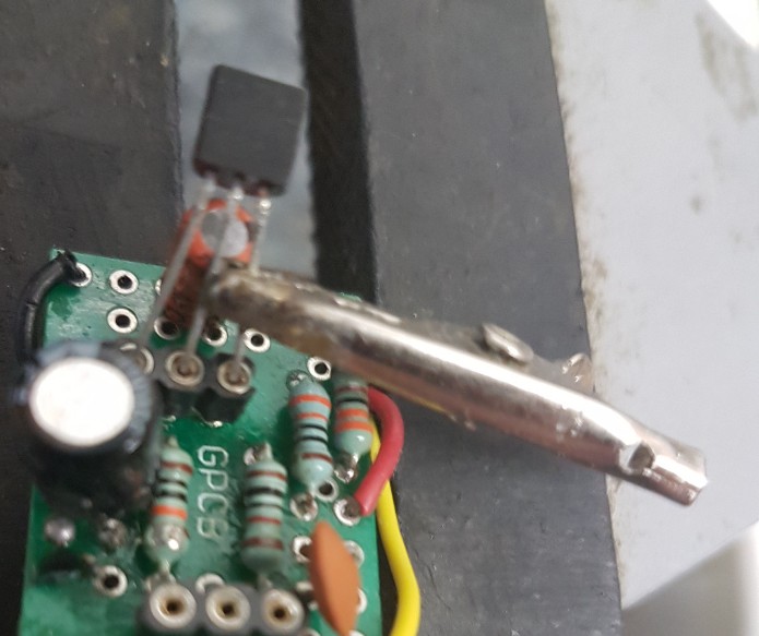
If my transistors feel loose in their sockets I use a small croc clip as a heatsink and solder one pin into the socket
If your transistors are in sockets it’s a good idea to do this then there’s no chance of them falling out when the pedals upside down or accidentally knocked or whatever
Like this clip the croc clip on a pin and put a blob of solder on your iron and carefully solder it in trying not to touch the plastic part of the socket
-
AuthorPosts


- You must be logged in to reply to this topic.