Your Source for DIY Pedal PCBs and NostalgiTone! › GuitarPCB Forum › GuitarPCB Build Support › Nostalgitone – 60s Edition
- This topic has 14 replies, 5 voices, and was last updated 6 months, 2 weeks ago by
 Tyrsoleen.
-
AuthorPosts
-
November 30, 2025 at 8:00 am #37953TyrsoleenParticipant
Hello,
I bought the NostalgiTone 60s 3-in-1 Combo kit from Musikding and soldered it together.
My question: I’m looking for a picture of a fully soldered circuit board so I can compare it to the others. Perhaps also a diagram showing which voltages should be applied where, so I can measure them.
Perhaps you could help me?
Best regards from Jena
Henri Wirth
November 30, 2025 at 8:27 pm #37954Jeff24ParticipantBoth of these threads have images of completed 60s combos:
December 1, 2025 at 12:02 pm #37956PlaysforfunModeratorThe voltages you are wondering about are simple actually. The Power and Switching schematic shows the incoming voltage of 9 volts and VC which is that same 9 volts but protected by D5 and filtered by C27 and C28. Actually VC is the voltage of whatever you are providing as the power source, whether a battery or adapter. The Fuzz schematic shows using that same VC and injecting it into the circuit between resistors R16 and R18. The Overdrive schematic shows that same VC and using it create VB1, over to the right side of the page. VB1 is the result of the voltage divider created by R13 and R14. Then VB1 is used throughout the Overdrive and measurable with your DMM at the points shown. That voltage divider having equal value resistors should yield exactly half of VC, presumably near 4.5 volts. The Tremolo introduces us to VD. VD will be a very very slightly reduced VC after passing through R37. So 9 volts and 4.5 volts (half of 9 volts) is what this board works with. Should troubleshooting become necessary because of how something behaves, other measurements according to expectations may then become necessary. Nothing to fret yet and hopefully not at all.
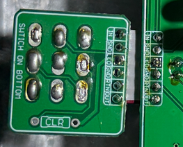
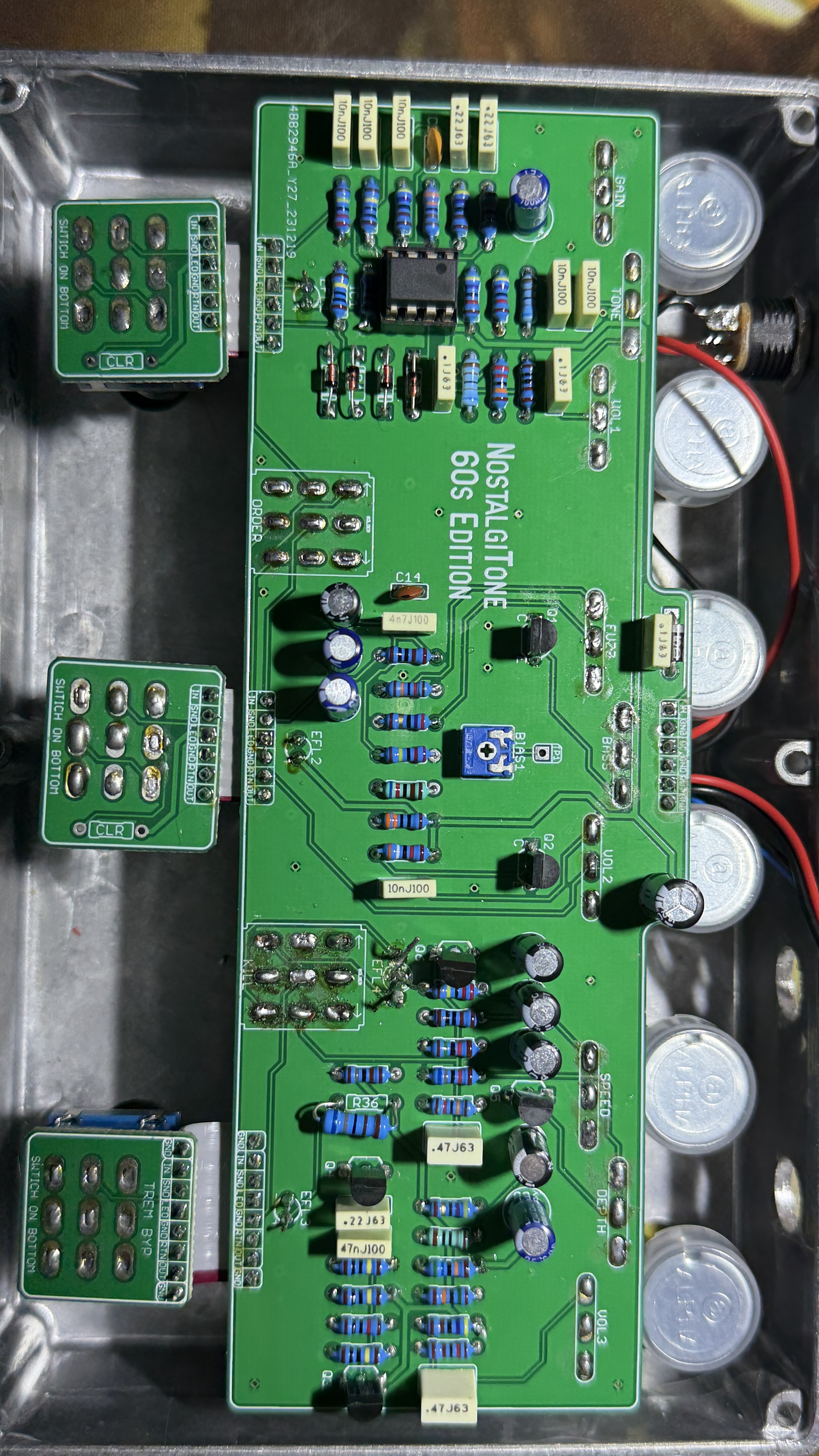
December 4, 2025 at 4:24 pm #37973TyrsoleenParticipantOkay, does anyone have any ideas and can help me? I’m completely stuck. I’m not a professional, but I really want to get this working. Basically, I get sound, the tremolo works, the volume is adjustable, the fuzz is incredibly harsh, and the overdrive is producing distortion. None of the LEDs are lit. The tremolo LED worked initially, but the others didn’t. The white LED only works if I reverse the positive and negative terminals at the input. Here’s a picture of my soldering. Danke … Henri
December 4, 2025 at 8:10 pm #37981PlaysforfunModeratorWelcome Henri. I can’t blame you wanting to get this working. It’s fantastic. You should go ahead and take it apart and fix any backward or blown leds. You are going to need to take the time to reflow all the switch and pot joints. Many look like cold joints that were soldered in haste. You will likely benefit from reflowing the rest of the board as well. As you do, remove the IC first and be super careful around and at the transistors so as not to cook them. Your soldering should result in a lot of shiny mounds shaped more like a hersheys kiss. Barry has a soldering video here someplace. I couldn’t find it just now. Take a look at the Guides Page, though, and scroll down to the guides below near the bottom. Read them all. Good info in there. How did it turn out matching your components up with the examples Jeff24 gave? All good there?
December 4, 2025 at 8:47 pm #37982AnonymousInactiveThe foot switch soldering looks suspect, there shouldn’t be a depression as the solder leads should poke up through the foot switch board, same goes for potentiometers; no need to trim leads once soldered. Also, you need CLR resistors (on foot switches) for Fuzz and OD. Cheers!
December 5, 2025 at 3:43 am #37983TyrsoleenParticipantHallo Zusammen,
vielen dank für die ehrlichen Antworten. Ich werde mich dann wohl oder übel an die Arbeit machen und messen.
Leider fehlten bei meiner Lieferung von http://www.musikding.de einige Teile.
Ein Widerstand, ein Potentiometer und möglicherweise diese beiden CLR Widerstände.
Ich halte Euch auf dem laufenden.
Gruß
HenriDecember 5, 2025 at 7:46 am #37985PlaysforfunModerator<span class="Y2IQFc" lang="de">Gehen Sie langsam und nehmen Sie sich Zeit (google translation). Just take your time.</span>
December 5, 2025 at 2:41 pm #37990BarryKeymasterI would suggest using some liquid solder FLUX when reflowing along with your solder.
There are many cold solder joints. Also be careful of the iron temperature.
Finally be sure you are using a fine conical tip when doing the small pads above the switch as some of them look like cold joints or limited solder.
For the larger switch pads place a small drop of flux on each pad and reflow the solder. You will not be able to force the switch in any closer but as long as you make a good solder connection you will be fine.
I always apply FLUX to switch lugs before soldering them to PCBs. It just makes everything better.
Most importantly, take your time, and be careful not to burn any solder pads or you will likely need a new PCB.
December 14, 2025 at 4:41 am #38050TyrsoleenParticipantHi everyone,
Thanks so much for your helpful tips. Yes, I need to resolder. Thanks Berry for the flux, I’ll do that. The overdrive and fuzz are already working… it’s a cool-sounding piece of kit.
Now I’m just waiting for the delivery of two missing parts, then I’ll tackle the tremolo.
And I’m kicking myself, it was working before, I practically broke it. But nothing is impossible. Just having this forum is incredibly helpful. A real source of inspiration.
I wish you all a wonderful holiday season. I’ll let you know when I have it completely up and running.
Cheers,
Henri
December 23, 2025 at 9:36 am #38111TyrsoleenParticipantHi everyone, I’ve resoldered everything and the overdrive and fuzz are working.
So far, so good. The tremolo only works briefly, for a few seconds. It does what it’s supposed to, but after a while, 20 to 50 seconds, sometimes even faster, the red LED stops blinking and stays on continuously; the tremolo effect is over.
Also, the LED for the toggle switch isn’t lit.
If I reverse the polarity of the power connection (positive and negative), the LED for the toggle switch lights up red and green, depending on the polarity. Could a component be faulty? I’ve checked all the connections… resoldered them…
Two problems. Has anyone experienced this? Can you help me remotely?
Thanks in advance, and yes, I have the time and will make the time. I can also take some photos.
Cheers,
Henri
December 23, 2025 at 12:34 pm #38112TyrsoleenParticipantHi everyone,
I just checked again and got out the soldering iron. There must have been another bad solder joint.
The tremolo works.
Only the toggle LED (tremolo on/off), not the footswitch itself, doesn’t light up—neither red nor green.
As mentioned before, if I reverse the input polarity, the pedal doesn’t work, but the LED then lights up red or green, depending on the switch position.
Could a transistor be soldered in backwards?
I already posted a picture of it above… strange. If anyone has any ideas, I’d be grateful.
Until then, enjoy the holidays.
Best regards,
Henri
December 24, 2025 at 1:07 pm #38117PlaysforfunModeratorGlad you got it working. That should be a relief just in time for the holidays. According to your post details the problem with the led is that it is the wrong type. There are Common Anode led’s and Common Cathode led’s for bi-color of RGB led’s. All of Barry’s boards need a common anode bi-color led. It’s all about polarity of the longest leg. I believe you have installed a common cathode led. Thats why if you reverse the polarity the led works with both colors. You need to replace it with the correct type. Common Anode is what you seek. Have a great holiday.
December 27, 2025 at 12:16 pm #38120TyrsoleenParticipantHello again,
thx very much … I have a good feeling … I try this
Grüße … Henri
January 17, 2026 at 5:10 am #38224TyrsoleenParticipantHi everyone,
Here’s my update on ending the thread.
I got an anode LED and soldered it in.
Thanks to your help, the device now works perfectly.
The sound settings are great. I’m thrilled.Thanks to everyone.
Cheers,
Henri
-
AuthorPosts

- You must be logged in to reply to this topic.