

@e-man
Forum Replies Created
-
AuthorPosts
-
 e_manParticipant
I have mine on my bench for quick reference. Along with the resistor reference and the wiring diagrams.
Good stuff.
July 29, 2022 at 7:40 am in reply to: Plexi Rebel – Plexi Plus, KoTB, Stage 3 Boost, ToneTweq, 2 Knob Job Combo #25616e_manParticipantI have been inspired by your combo build! I’ve built a combo using a BEOD and a Tight Box with a Sho’Nuff Booster. I used a loop switching PCB from another company to achieve the “channel” switching between the BEOD & the Tight Box.
I was wondering if you could elaborate on how you used the 2KJ to perform “channel switching”.
I can’t see enough detail in your gut shots to determine how it was wired.
Thanks for any help you can give.
e_
July 26, 2022 at 11:04 pm in reply to: Could a 2 Knob Job be used to create a channel switching setup? #25577e_manParticipantForgive me wilkie1, I shouldn’t have typed lugs 7 & 9, should have typed 3 & 9.
On the pcb I have. lugs 3 & 9 are tied together and I didn’t find a solder pad that was connected to them.
Sorry for the confusion.
Thanks.
July 26, 2022 at 5:41 pm in reply to: Could a 2 Knob Job be used to create a channel switching setup? #25569e_manParticipantthe 3PDT GPCB board I have has lugs 7 & 9 tied together with no solder pad tied to them.
I don’t think that’s going to work for me. I need 7 & 9 for the second effects send and return.
Think I’m gonna have to skip the PCB.
July 26, 2022 at 7:37 am in reply to: Could a 2 Knob Job be used to create a channel switching setup? #25558e_manParticipantThanks wilkie1!
Had a “Duhhh” moment when I first saw your response.
Do you think there would be a need to ground the “off” channel to prevent popping or noise?
Thanks again for your help.
May 4, 2022 at 4:26 pm in reply to: So is there a trick to soldering board mounted pots? No melted caps… #24400e_manParticipantThanks for your responses guys. I was really more venting than anything.
Bruce R. please don’t think I was being critical of the boards layout or design. While I only have a limited knowledge of things electronic, I appreciate the challenges of laying these PCB’s out and think you do a great job.
As I said, I really prefer board mounted pots and if the tight fit is a part of the deal then it’s worth it. I have some narrower tips for my iron so perhaps I’ll give that a try.
this is a pot style I was considering giving a try. They would solder on the same side as all of the other components. I would just need to check the leg length compared to enclosure depth. Would also have to pay attention to leg orientation so that leg 1 is in the correct spot.I would like to say to each of you, (Barry, wilkie1 and Bruce R.) I appreciate this site and the GuitarPCB business as a whole. This is great resource for me and look forward to building some great stuff in the future.
Currently I’m working on a combo of Tight Box, Cranky Charles, and a SHO’Nuff booster. Independent booster with A/B switching between the two Marshall sounds. It’s gonna be killer when i get it done.
Thanks again for all you guys do.
Later.
e_manParticipantSorry to take so long to respond.
I just installed a 150k at R5 and there is definitely a difference in switch positions now!
I might should have gone with 220k but figured I’d split the difference.
Thanks for your help Barry, this really is a great sounding circuit.
e_manParticipantI’m having the same troubles with my T-Drive. The switch makes no difference.
I don’t have a rheostat on hand. (I do have some trim pots though)
Do you have a feel for what resistor value would be close to your setting? I can’t really determine the position of Oscar’s rheostat, as well as not being able to determine the approximate resistance even if I could! (not really a total newb, but still trying to grasp basic electronics) I’m guessing he used your recommended 20k.
If a trim pot can be used, can you advise me on how to wire it? You know with the 3 legs and all…
Thanks for any help you can give.
BTW this pedal sounds great!
e_manParticipantThanks Billy. I went ahead and put it together using the A500.
It sounds good though. The gain control doesn’t seem to be problematic so I’ll probably leave it.
The pedal sounds good. There just doesn’t seem to be much difference in the switch positions. Don’t really hear the “hot” setting. I saw something on the forum about someone else having this trouble. I’ll change some resistors at R5 and see if it helps.
Thanks for your help.
e_manParticipant10:4.
Thanks Billy.
e_manParticipantThanks for the info Barry.
I appreciate the work you put into these circuits. I’ll be checking the grounding and reflowing the joints.
Right now, I’m running the transistors spec’d in the build documents. I think I’ll experiment with some other transistors.
Thanks again for the info.
e_manParticipantI found the problem.
Oner of the pads on R3 (the end towards the center of the board) had separated from the trace on the board. The circuit was open after that point on the board. You can see the bare copper in the photo I posted above. Just couldn’t see the forest for all of the trees.
I found it using a sound source (little mp3 player) and a meter probe to work my way through the circuit. When i got to the second end of R3 I had sound.
I drug solder over onto the bare copper trace and all is good.
I have to say, the pedal’s not bad, but the sag control is something I’m still figuring out.
And this thing is really noisy! Maybe I can experiment with pedal order and help some of that.
Has anyone else that has built this one has any of these troubles?
Thanks everyone for your help.
e_manParticipantHere’s a little better pic.
Thanks.
e_manParticipantWell, I haven’t had it in an enclosure yet (I have it drilled and ready but have not installed it).
I’ll check R2 & R4.
Thanks for your help.
e_manParticipantThanks for your comment Billy.
I connect my guitar to the input on the board and I connect my amp input to the output on the board. I have a temp DC connection to power it. I should get the effected signal from the board.
I don’t usually install a board in an enclosure until I hear it work. The footswitch is on a pcb of its own, so it’s pretty straightforward.
I know there’s only so much to glean from the photos, I was just hoping for something obvious.
I’ll try to get some better pics up tomorrow.
Thanks again.
e_manParticipantThanks for your comments graham.
i’m sorry i forgot to mention that i had the connection colors reversed on the input on the board. A mistake I left uncorrected to prevent one more soldering/unsoldering on the board.
I am connecting it accordingly when testing.
Thanks,
-
AuthorPosts
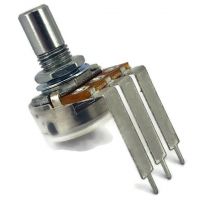 this is a pot style I was considering giving a try. They would solder on the same side as all of the other components. I would just need to check the leg length compared to enclosure depth. Would also have to pay attention to leg orientation so that leg 1 is in the correct spot.
