Can someone provide a picture of how the Q1 should installed for both a metal and regal 2n2222? All the holes are a bit confusing for me rather than just seeing three. A picture showing where each leg goes and orientation would be fantastic.
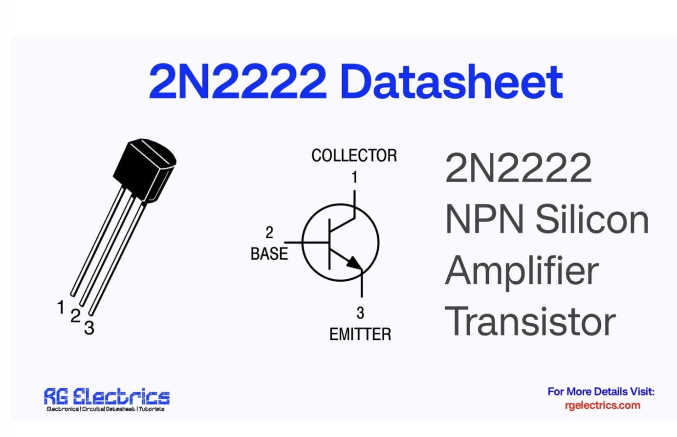
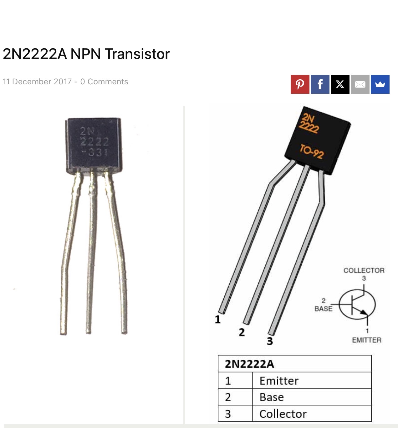
When in doubt socket! The three center holes top to bottom are for the Base. Find the data sheet for your transistor to determine Emitter from Collector. A gut shot could throw orentation off unless you have the same transistor. Here are two data sheets showing opposite legs for 1 & 3:
Here is a pinout for a metal can type 2N2222. The leg closest to the tag should go to the E pad on the board if using this type.
It’s handy to have a component tester to identify component leads. ( I use an Atlas DCA55 ) it can save time instead of searching for datasheets. Hope that helps.
 .
.